Systems and Arrangements for Controlling an Impedance on a Transmission Path

Inactive Publication Date: 2008-05-29
IBM CORP
View PDF6 Cites 57 Cited by
  • Summary
  • Abstract
  • Description
  • Claims
  • Application Information

AI Technical Summary

Benefits of technology

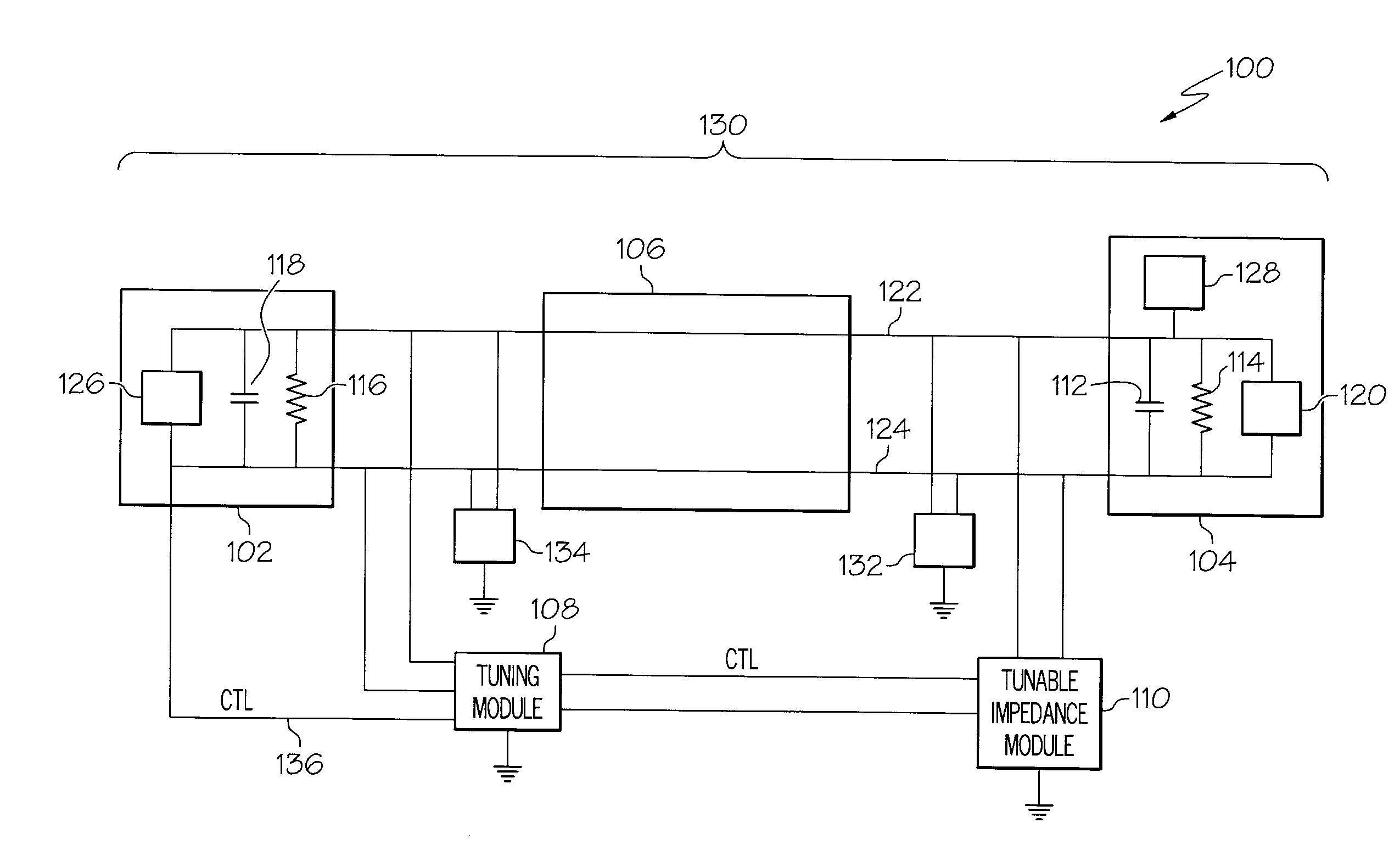
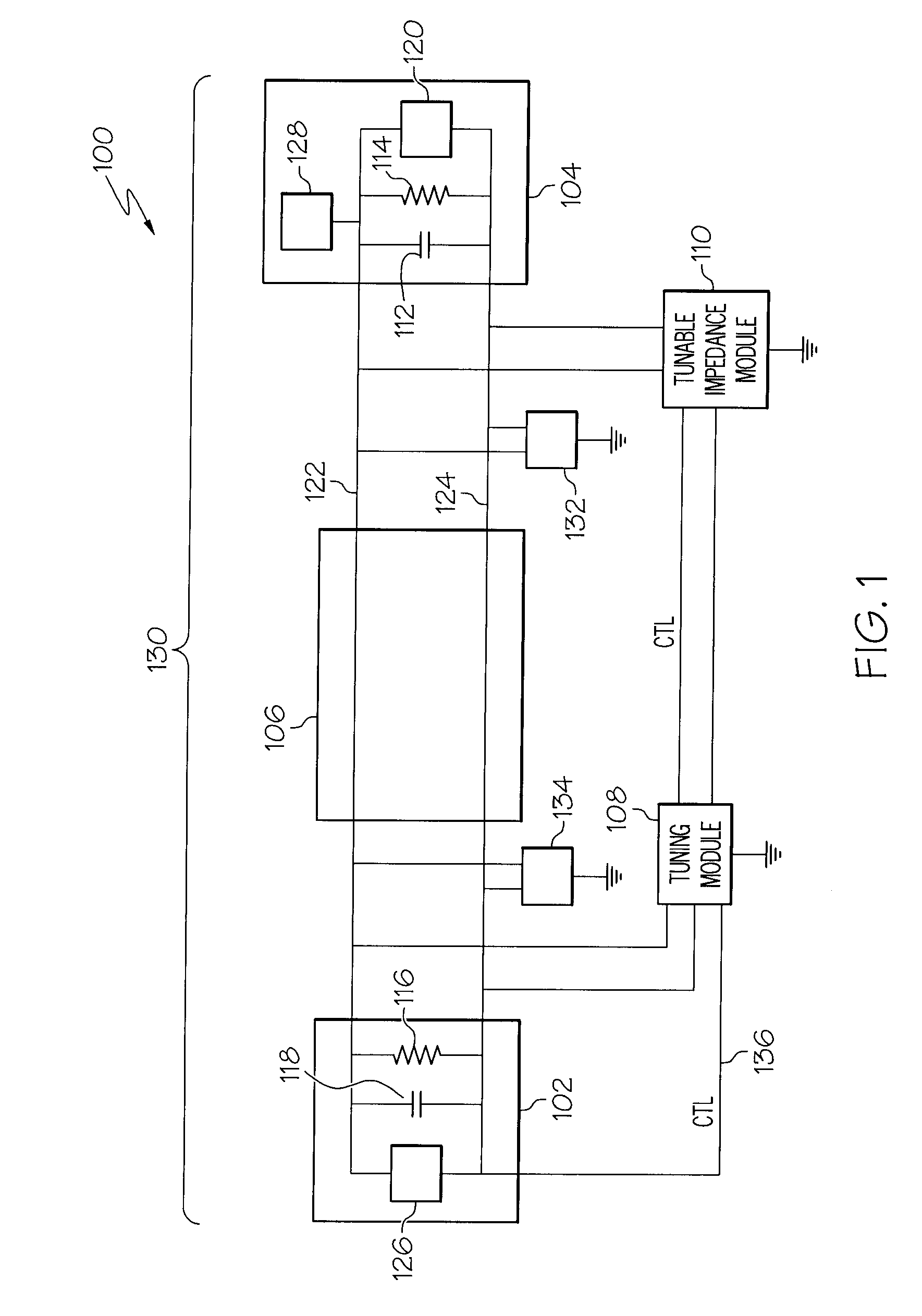
[0014]In another embodiment a transmission line tuning apparatus is disclosed. The apparatus can include a transmission path having a first connection proximate to a first transmitter termination and a second connection proximate to a second termination that is proximate to a receiver. The apparatus can include a transmitter coupled to the first connection to transmit a test signal over the transmission path and a tunable impedance module coupled to the transmission path proximate to the second termination. An impedance tuning module can be coupled to the tunable impedance module and to the transmission path to monitor reflected signal energy on the transmission path resulting from the test signal. Impedance tuning module can control the tunable impedance module in response to the monitored reflected signal energy such that changing a setting of

Problems solved by technology

To maximize performance, the value of the termination resistor is carefully selected, but component and manufacturing tolerances can skew this resistance value.
Further, unwanted and unavoidable parasitic load capacitances are typically present at numerous locations along the transmission path.
The capacitance becomes a significant problem at higher frequencies and such capacitance can distort the data waveform from its intended shape such that the data on the waveform becomes unreadable by a receiver.
When such distortion occurs, it is difficult to read data or recover data from the incoming waveform.
Therefore, when multiple mismatches occur not only is the shape of the eye patterns distorted but also random noise, cross talk a

Method used


Image

  • Systems and Arrangements for Controlling an Impedance on a Transmission Path
  • Systems and Arrangements for Controlling an Impedance on a Transmission Path
  • Systems and Arrangements for Controlling an Impedance on a Transmission Path

Examples


Embodiment Construction

[0028]The following is a detailed description of embodiments of the disclosure depicted in the accompanying drawings. The embodiments are in such detail as to clearly communicate the disclosure. However, the amount of detail offered is not intended to limit the anticipated variations of embodiments; on the contrary, the intention is to cover all modifications, equivalents, and alternatives falling within the spirit and scope of the present disclosure as defined by the appended claims. The descriptions below are designed to make such embodiments obvious to a person of ordinary skill in the art.

[0029]While specific embodiments will be described below with reference to particular configurations of hardware and / or software, those of skill in the art will realize that embodiments of the present invention may advantageously be implemented with other equivalent hardware and / or software systems. Aspects of the disclosure described herein may be stored or distributed on computer-readable med...


PUM


Abstract

Systems for making impedance adjustments that will auto-tune a communication path is disclosed. The method can utilize time domain reflectometry (TDR) to acquire data about impedance mismatches and can adjust the termination impedances based on the acquired data. A system is also disclosed that has an isolator to decouple a first adjustable resistor from a transmission path in a first mode and couple the first adjustable resistor to the path in a second mode. The system can have a test transmitter to create a first current on the path in the first mode and to create a second current having twice the current in a second mode, wherein a detector can detect a first voltage during the first mode and a second voltage in the second mode as the first adjustable resistive load is adjusted in the second mode until it reaches a value matching the first voltage detected in the first mode.

Description

FIELD OF INVENTION[0001]The present disclosure is related to the field of signal propagation and more particularly to the field of impedance matching for a communication system transmission path.BACKGROUND[0002]High-speed serial communication links are often utilized to convey data from integrated circuit to integrated circuit or from “chip-to-chip.” A basic system can have a transmitter that is integrated on the chip, which can send data over the transmission path, such as a transmission line, wherein the transmitted data can be acquired by a receiver. In state-of-the-art communication systems, transmitters and receivers are often placed in an integrated circuit and integrated with other functional sub-systems systems on the chip, to minimize the space required to implement a communication system. The transmission path can include conductive media such as a backplane, a cable or a printed circuit board.[0003]The printed circuit board can be made of many different materials includin...

Claims


Application Information

Patent Timeline
IPC IPC(8): H04B15/00H03H7/40
CPCH04L25/0278
Inventor CRANFORD, HAYDEN C.FRIEDMAN, DANIEL J.MASON, JAMES S.SCHMATZ, MARTIN L.SORNA, MICHAEL A.TOIFL, THOMAS H.
Owner IBM CORP
Why Eureka
Try Eureka