Molecular interferometric imaging process and apparatus

a technology of interferometry and molecular structure, applied in the direction of phase-affecting property measurement, sampling, instruments, etc., can solve the problems of inability to pipe through flow-cells, incompatible laser scanning interferometric approaches with real-time kinetic capture of wet samples, time-consuming, etc., to achieve high sensitivity, high speed, and high-resolution optical detection

Active Publication Date: 2008-06-05
PURDUE RES FOUND INC
View PDF99 Cites 15 Cited by
  • Summary
  • Abstract
  • Description
  • Claims
  • Application Information

AI Technical Summary

Benefits of technology

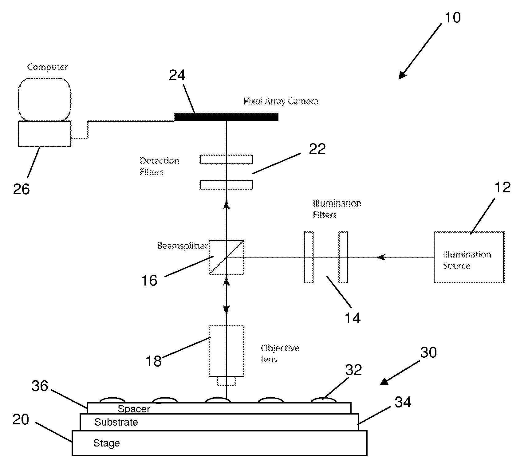
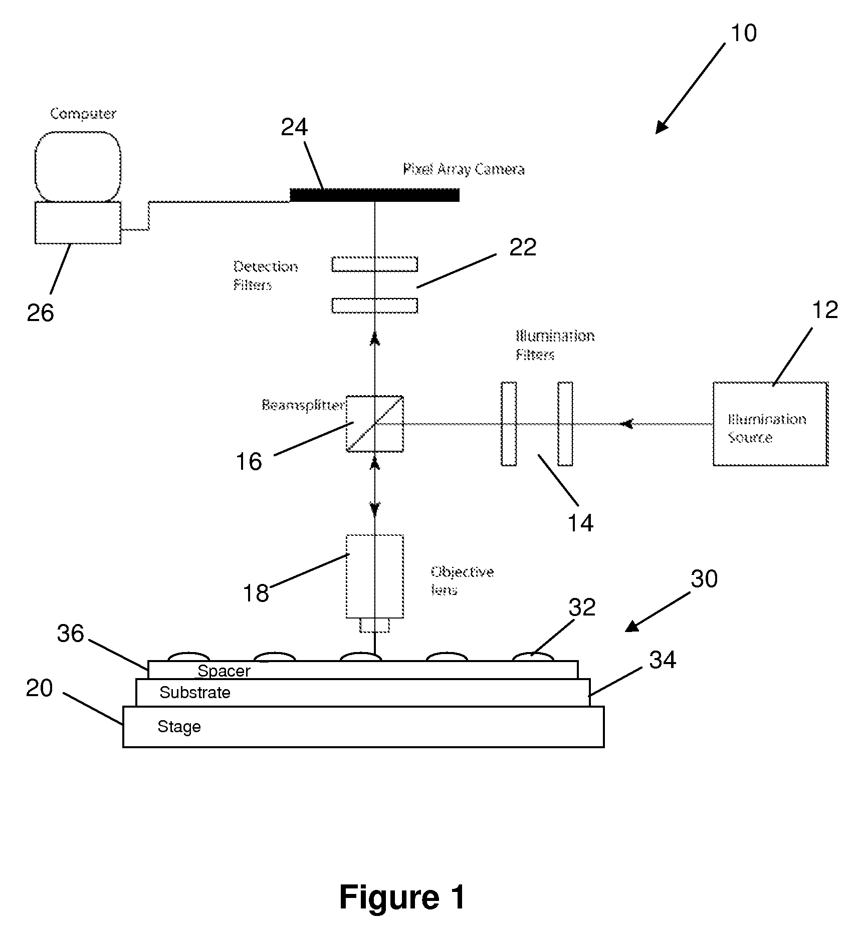
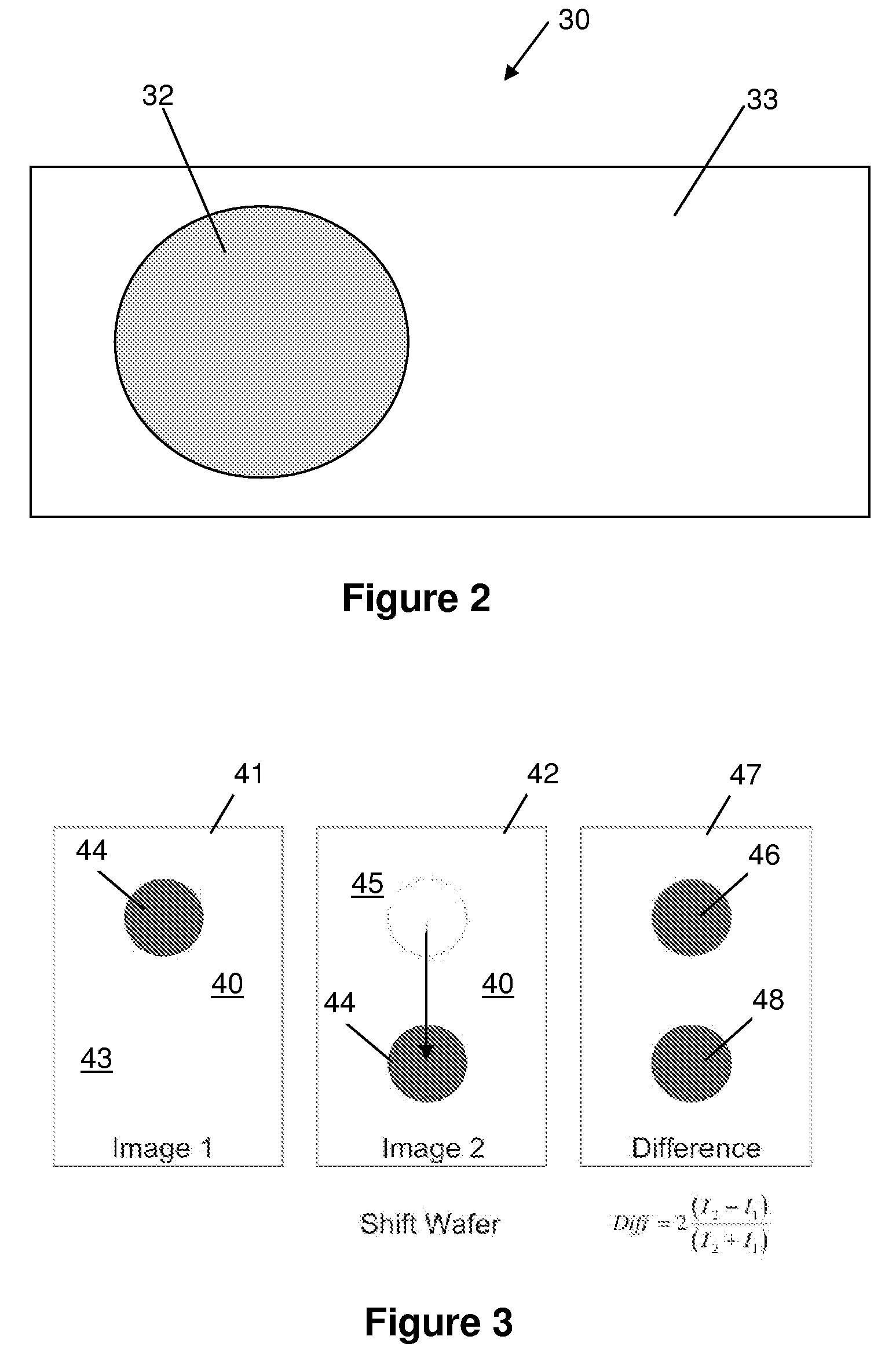
[0002]The present invention generally relates to obtaining direct images of biological molecules distributed on surfaces designed to convert molecular phase to reflected intensity. The reflected intensity is linearly proportional to protein density. Normally invisible biological molecules are made visible by the condition of in-line interferometric quadrature established by the substrate that transduces phase to intensity. The basic principle of operation is shearing in-line common-path interferometry in which a digital interferometric image of patterns of biological molecules is acquired and referenced to a reference surface by two image acquisitions. The technique has the advantage of high speed, high sensitivity and high-resolution optical detection of biological molecules.

Problems solved by technology

Moreover, while conventional laser scanning techniques are time-consuming when obtaining high-resolution scans of protein spots, as well as incompatible with disc wobble when scanning spots under high magnification, the present system minimizes these problems by acquiring numerous pixels in a single exposure.
Conventional laser scanning interferometric approaches are also incompatible with real-time kinetic captures from wet samples, particularly as flow-cell plumbing is impossible, except for the use of centrifugal force to move fluids.
SPR systems, on the other hand, are sensitive to thicknesses and require tightly constrained wavelengths and angles.

Method used


Image

  • Molecular interferometric imaging process and apparatus
  • Molecular interferometric imaging process and apparatus
  • Molecular interferometric imaging process and apparatus

Examples


Embodiment Construction

[0028]The embodiments of the present invention described below are not intended to be exhaustive or to limit the invention to the precise forms disclosed in the following detailed description. Rather, the embodiments are chosen and described so that others skilled in the art may appreciate and understand the principles and practices of the present invention.

[0029]This application is related to U.S. patent application Ser. No. 10 / 726,772, entitled “Adaptive Interferometric Multi-Analyte High-Speed Biosensor,” filed Dec. 3, 2003 (published on Aug. 26, 2004 as U.S. Pat. Pub. No. 2004 / 0166593), which is a continuation-in-part of U.S. Pat. No. 6,685,885, filed Dec. 17, 2001 and issued Feb. 3, 2004, the disclosures of which are all incorporated herein by this reference. This application is also related to U.S. patent application Ser. No. 11 / 345,462 entitled “Method and Apparatus for Phase Contrast Quadrature Interferometric Detection of an Immunoassay,” filed Feb. 1, 2006; and also U.S. p...


PUM

PropertyMeasurementUnit
thicknessaaaaaaaaaa
heightaaaaaaaaaa
heightaaaaaaaaaa

Abstract

A molecular interferometric imaging system for detecting an analyte in a sample, that includes an illumination source providing a beam of radiation; a pixel array for detecting radiation in an image plane; a biolayer designed to react to the analyte when it comes in contact with the sample; a substrate designed to convert phase modulation into intensity modulation which can be detected and imaged directly by the pixel array, the biolayer being on the substrate; a reference surface; an image switching means for switching between a first position for collecting a sample image of the biolayer, and a second position for collecting a reference image of the reference surface; and a processing means for producing a composite image using the sample image and the reference image for illumination normalization.

Description

CROSS-REFERENCE TO RELATED APPLICATIONS[0001]This application claims the benefit of U.S. Provisional Application Ser. No. 60 / 867,961, filed on Nov. 30, 2006, entitled “Molecular Interferometric Imaging Process and Apparatus,” which is incorporated herein by reference.BACKGROUND AND SUMMARY[0002]The present invention generally relates to obtaining direct images of biological molecules distributed on surfaces designed to convert molecular phase to reflected intensity. The reflected intensity is linearly proportional to protein density. Normally invisible biological molecules are made visible by the condition of in-line interferometric quadrature established by the substrate that transduces phase to intensity. The basic principle of operation is shearing in-line common-path interferometry in which a digital interferometric image of patterns of biological molecules is acquired and referenced to a reference surface by two image acquisitions. The technique has the advantage of high speed,...

Claims


Application Information

Patent Timeline
Patent Type & Authority Applications(United States)
IPC IPC(8): G01N1/00
CPCG01N21/45G01N21/253
Inventor NOLTE, DAVID DZHAO, MING
Owner PURDUE RES FOUND INC
Why Eureka
Try Eureka