Apparatuses, Systems, and Methods Utilizing Laminar Flow Interface Control and for Controlling Laminar Flow Interface

Inactive Publication Date: 2008-06-05
CARNEGIE MELLON UNIV
View PDF1 Cites 17 Cited by
  • Summary
  • Abstract
  • Description
  • Claims
  • Application Information

AI Technical Summary

Benefits of technology

[0021]Examples of investigations that may be performed using the present invention include, but are not limited to, studies of inter-cellular signaling to experiments with nutrient uptake and studies of the cell growth cycle to experiments with cell-in-the-loop control. Control over the time history of input signals and measurement of time history of outputs is fundamental to the engineering approach for modeling a dynamic system. In one embodiment of the present invention, the manipulated input will be the spatiotemporal chemical environment of a cell or populations of cells. Several outputs could be measured automatically, possibly simultaneously, of both individual cells and cell populations, including spatiotemporal intensity from fluorescence chemical probes and the position of the cell. One advantage of the present invention is the ability to flow dissimilar mixtures next to each other in a microfluidic channel without turbulent mixing of the constituent chemicals.

Problems solved by technology

The complexity and small size of cells limit one's ability to study these highly intricate systems.
Cells are in a constant state of feedback and response to varying environmental factors, and the classic experimental methodology of altering a single variable while holding all others unchanged can be prohibitively challenging, forcing researchers to resort to compound or highly indirect experiments, often on populations of cells.
A considerable amount of processing and data interpretation is needed to interpret the results of such experiments.
However, black-box approaches to probing and modeling the dynamics of cellular processes have been essentially impossible due to the absence of experimental systems to acquire quantitative input / output time series data.
The dearth of technologies for quantitative high-throughput experiments is attributable to the small size and tremendous complexity of biological cells.
The lack of such quantitative experimental systems has hampered system biology and other biological and medical sciences.
However, one significant difference between the two domains is that there is generally no separate control unit in a biological regulation process.
Hampering the contribution of engineers to biology has been the lack of techniques to provide chemical inputs and measure cell responses with sufficient temporal and spatial resolution to generate quantitative time series data for system identification.
At both extremes, human manipulation of inputs and measurement of outputs is impractical, motivating the development of automated systems for acquiring time series data.
The ability to determine the functioning of a single cell has been handicapped by the absence of technology to introduce spatiotemporal stimulation to localized subcellular domains with single cells of sub-micron specificity.
Patch clamping, micropipetting, and laser microsurgery are useful for examining local domains, but none of these methods have the potential to be as robust as those enabled by a micro- and nano-technological approach.

Method used


Image

  • Apparatuses, Systems, and Methods Utilizing Laminar Flow Interface Control and for Controlling Laminar Flow Interface
  • Apparatuses, Systems, and Methods Utilizing Laminar Flow Interface Control and for Controlling Laminar Flow Interface
  • Apparatuses, Systems, and Methods Utilizing Laminar Flow Interface Control and for Controlling Laminar Flow Interface

Examples


Embodiment Construction

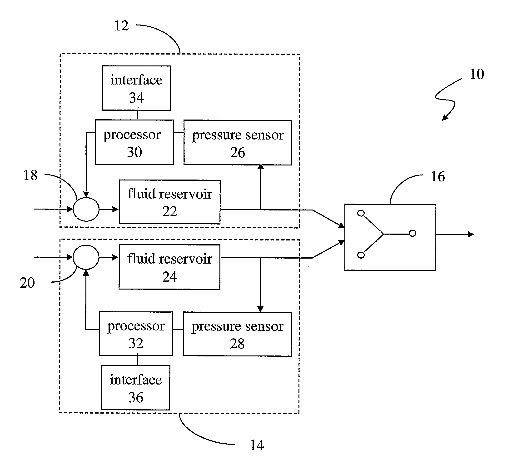
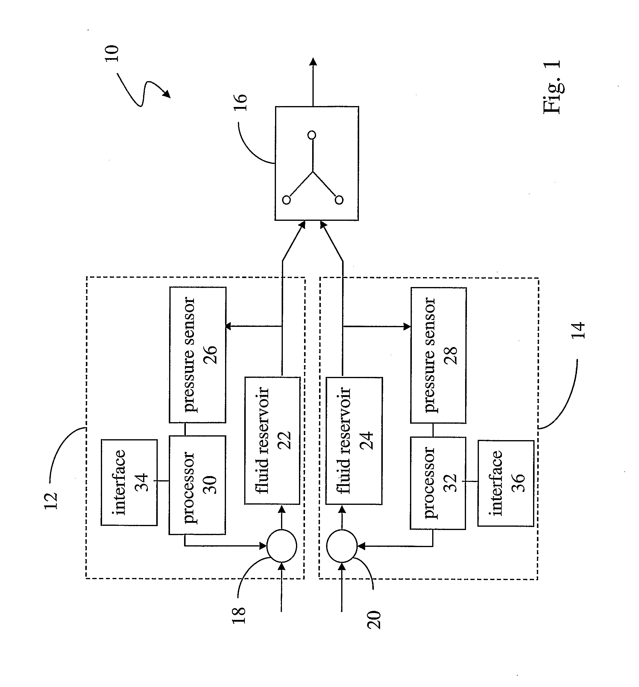
[0043]The present invention is generally applicable to the field of fluidics, and is particularly relevant to the field of microfluidics and the control of a laminar flow interface. The present invention will generally be described in terms of controlling the chemical environment of a cell. However, the present invention is relevant to a much wider range of technologies and applications, such as the manufacture and operation of microdevices or Microsystems such as micro-electromechanical systems, semiconductor fabrication, molecular self-assembly, and other technologies and applications.

[0044]In one embodiment, the present invention can be used for actively controlling cells' chemical environments with subcellular precision and time-domain variability. For example, the present invention can be used to aid the transmission of time varying chemical signals to cells. Because the fluid flow is incompressible at certain pressures, including those used in these applications, flow rate thr...


PUM


Abstract

Apparatuses, systems, and methods for controlling the position of the interface between two or more laminar flow stream in a microfluidic device. In one embodiment, an apparatus includes a first fluid reservoir shaving an output, a first pressure sensor connected to the output of the first fluid reservoir, a first actuator connected to the first fluid reservoir, a feedback loop connected between the first pressure sensor and the first actuator, a second fluid reservoir having an output, a second pressure sensor connected to the output of the second fluid reservoir, a second actuator connected to the second fluid reservoir, a feedback loop connected between the second pressure sensor and the second actuator, and a microfluidic device including a first input connected to the output of the first fluid reservoir, a second input connected to the output of the second fluid reservoir, and an output. In another embodiment, a method includes sensing fluid pressure from a first fluid reservoir connected to a first input of the microfluidic device, adjusting a first actuator in response to the fluid pressure in the first fluid reservoir, sensing fluid pressure from a second fluid reservoir connected to a second input of the microfluidic device, and adjusting a second actuator in response to the fluid pressure in the second fluid reservoir.

Description

CROSS-REFERENCE TO RELATED APPLICATIONS[0001]This application claims priority from U.S. Provisional Patent Application No. 60 / 618,147, filed Oct. 13, 2004, which is incorporated herein by reference.FIELD OF THE INVENTION[0002]The present invention is directed to the field of fluidics and is particularly relevant to the field of microfluidics and for controlling laminar flow interfaces.BACKGROUND OF THE INVENTION[0003]The complexity and small size of cells limit one's ability to study these highly intricate systems. Cells are in a constant state of feedback and response to varying environmental factors, and the classic experimental methodology of altering a single variable while holding all others unchanged can be prohibitively challenging, forcing researchers to resort to compound or highly indirect experiments, often on populations of cells. A considerable amount of processing and data interpretation is needed to interpret the results of such experiments. The accomplishments of mod...

Claims


Application Information

Patent Timeline
IPC IPC(8): B01J19/00G05D7/06G05D11/02
CPCB01L3/502769B01L2200/0636B01L2200/0647B01L2200/146G01N15/147B01L2300/0864B01L2300/0867B01L2400/0487B01L2300/023Y10T137/2531Y10T137/2663
Inventor KUCZENSKI, M. BRANDONMESSNER, WILLIAM CHARLES
Owner CARNEGIE MELLON UNIV
Why Eureka
Try Eureka