Method, System and Apparatus for Simulating Fluid Flow in a Fractured Reservoir Utilizing A Combination of Discrete Fracture Networks and Homogenization of Small Fractures
Active Publication Date: 2008-06-05
CHEVROU USA INC
View PDF44 Cites 174 Cited by
Summary
Abstract
Description
Claims
Application Information
AI Technical Summary
This helps you quickly interpret patents by identifying the three key elements:
Problems solved by technology
Method used
Benefits of technology
Benefits of technology
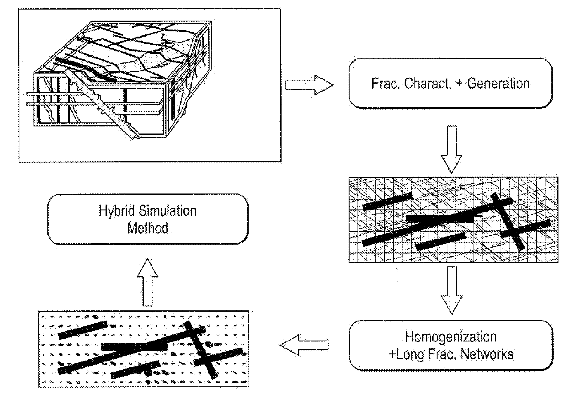
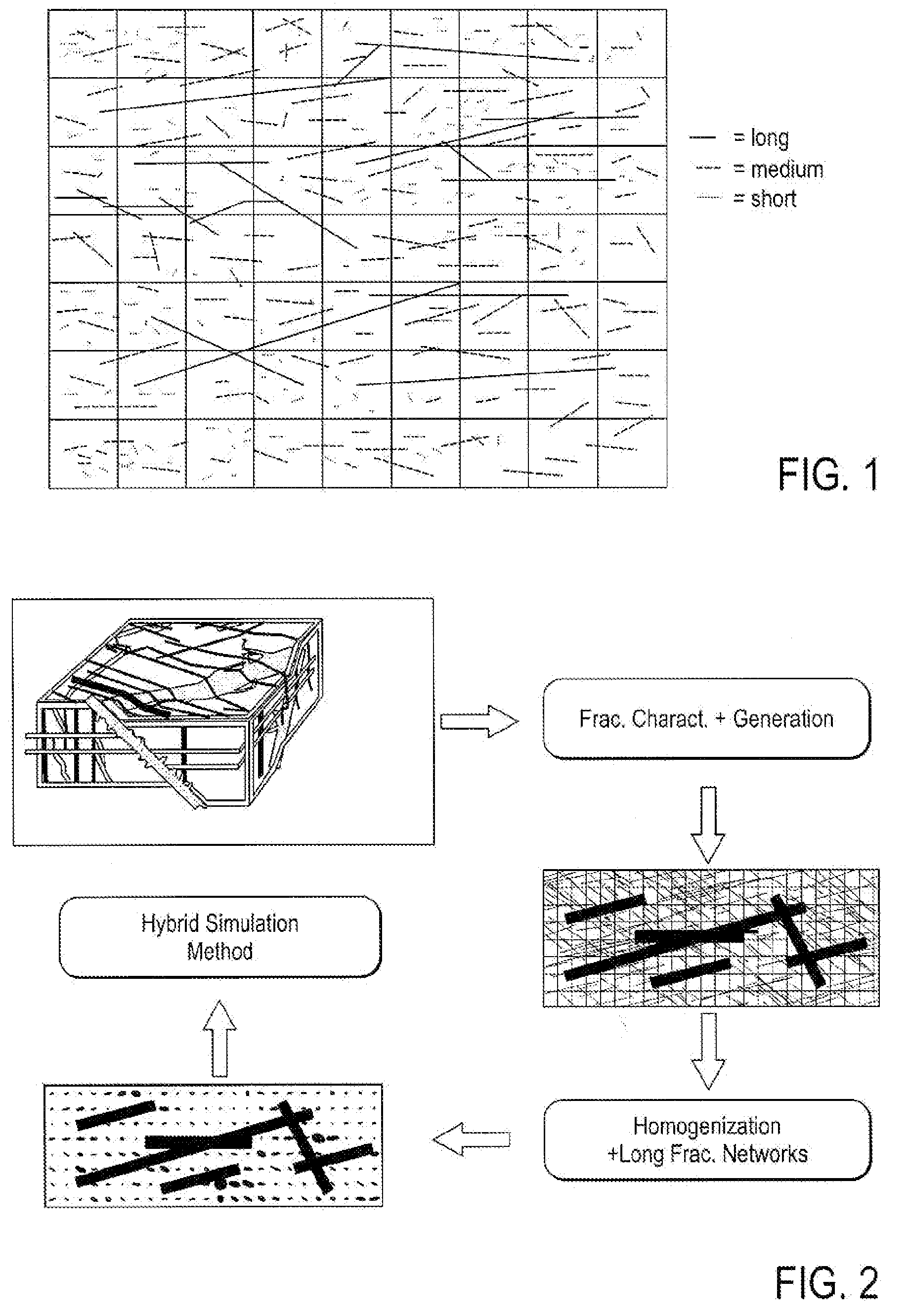
[0009]Two-dimensional fracture blocks are used which ideally overly and are fluidly connected to underlying matrix blocks. The long fractures may be in direct in fluid communication with one or more intersecting wells. Where long fractures intersect with one another, the intersection of the long fractures may be modeled as a point source to enhance numerical stability during simulation. The hybrid reservoir model may utilize networks of fractures in conjunction with an underlying grid of matrix blocks wherein fracture characteristics such as (1) orientation; (2) fracture aperture; (3) fracture length; and (4) fracture height are more realistically modeled than in previously known reservoir models.
[0012]The two-dimensional fracture blocks are ideally defined by two opposing plates with an aperture defined there between. The two-dimensional long fractures preferably have lengths and heights which are representative of the fractures in the fractured reservoir being modeled to honor the physical orientation of estimated fractures in the fractured reservoir being modeled. A transport index may be used to fluidly couple the matrix blocks to the respective fracture blocks in which the fracture blocks are disposed. Where at least two of the long fractures intersect with one another to form an intersection, the intersection may be modeled as a source or sink term to enhance the stability of the solving of the flow equations. The reservoir model ideally includes means for direct matrix block to fracture block fluid communication, direct matrix block to well fluid communication and direct fracture block to well block communication.
[0028]A further object is to model fractures using networks of long fractures wherein the long fractures intersect with one another, the intersection of the long fractures being modeled as a point source to enhance numerical stability during simulation.
Problems solved by technology
However, due to the limited length of fractures in such artificially fractured reservoirs, the computational advantages offered by the present invention are not nearly as great as in very large scale naturally fractured reservoirs.
Even though fractures are the most abundant visible structural feature in the Earth's upper crust, the fracture characterization of a reservoir is very challenging because the full distribution of fractures in the reservoir condition is practically not measurable.
Fracture systems are typically very irregular, often disconnected and may occur in swarms.
A common difficulty, in addition to a wide variation of fracture length scale, when modeling flow in fractured reservoirs, is that there are usually too many fractures to be explicitly included in a flow model.
Furthermore, the long fractures whose length scale is much larger than the grid size should be modeled explicitly because any homogenization method, i.e., using an effective medium method, will typically underestimate the effect of these important geological features.
This is inefficient.
This results in underestimated values for the computed effective permeabilities.
In addition, the discretization results in geometrical symmetries leading to instances where the same integrals appear in different equations.
Although the extent of fracture network cannot be easily verified, a significant increase in well productivity unequivocally indicates that the well is in connection with a network of fractures.
This obviates the need for a very small block to model the fluid flow of intersecting fractures which can lead to numerical instability.
Method used
Image
Click on the blue label to locate the original text in one second.
Reading with bidirectional positioning of images and text.
Examples
example 1
Single Long Fracture Model
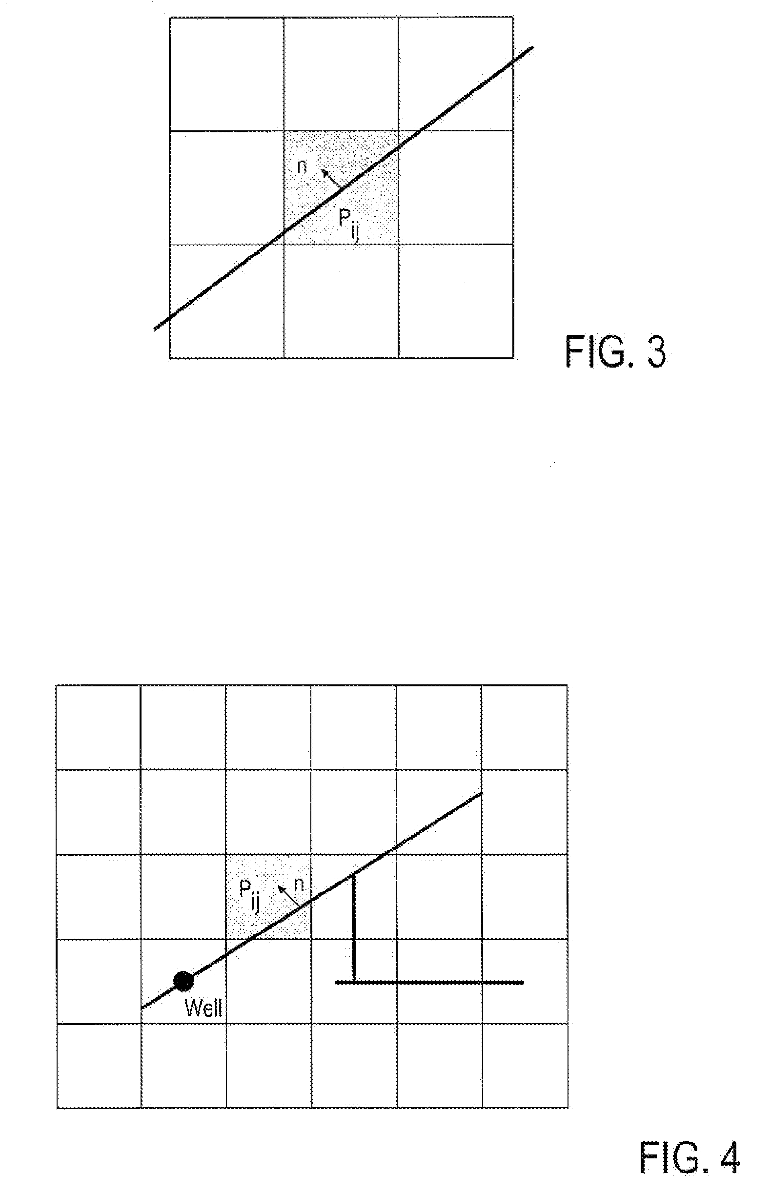
[0126]In a first example, a quarter of five-spot configuration is examined, in which the flow is driven by a source and a sink placed at the opposite corners of a three-dimensional domain. The model has dimensions of 500 ft×500 ft×9.9 ft, discretized equally by 20×20 grid blocks horizontally and 3 blocks vertically. This results in 1200 regular grid blocks with each block of dimension 25 ft×25 ft×3.3 ft. The short and medium fractures are generated from a stochastic process and are shown in FIG. 6 for Layers 1, 2, and 3. The areal or top view of the second layer of the model is shown in FIG. 7.
[0127]In FIG. 7, a long fracture is included which extends from cell (6, 6) to cell (15, 15), in the second layer to demonstrate how to model a long fracture as a major fluid conduit. The matrix permeability is km−1 md and the fracture permeability is kf=1000 Darcy and the transport index is TIi=4270 ft3 / day ft.
[0128]Following the hierarchical framework, the effective...
example 2
A Network with Three Connected Long Fractures
[0131]Based on the settings in the previous example, two other long fractures are added, from cell (6, 10) to cell (15, 10), and from cell (14, 14) to cell (14, 18), to connect the original long fracture and form a small fracture network, shown in FIG. 10. The fracture permeabilities in these newly added long fractures are the same as the previous one, as are the transport indices.
[0132]FIGS. 11 and 12 are water saturation maps of the second layer in the heterogeneous and homogeneous systems with a network of long fractures at t=0.254 PVI. These maps confirm that the present method of numerical simulation captures the phenomena described in the previous example. As expected, the fracture network picks up the displacing fluid from upstream ends and transport from the connected fractures to form multiple fronts in the downstream. The enhanced matrix permeability due the presence of small / medium fractures increases fluid transport in matrix,...
example 3
A Network of Long Fractures Intersecting an Injection Well
[0133]In the following three examples, a reservoir model is constructed which is 5000 ft×5000 ft×300 ft. in dimension. The top of the reservoir is 8325 feet deep and the model is discretized uniformly by 10×10 grid blocks in the horizontal plane and by 3 matrix blocks in the vertical cross-section. The initial oil saturation is assumed to be 1 in the whole domain. A quarter of a five spot pattern is applied in this bounded three-dimensional example. FIG. 13 shows the grids of the model and the locations of the injection well (1, 1, 3) and production well (10, 10, 1). Gas is injected at a constant rate, 10000 MSCF / day, and the bottom hole pressure of the producer is maintained at 4000 psi. The matrix permeabilities and porosities used in these examples are listed in Table 1.
[0134]In this example, two long, intersected fractures are included that cut through all three layers, as shown in FIG. 13. Note that all fractures are ass...
PUM
Abstract
The present invention includes a method, system and apparatus for simulating fluid flow in a fractured subterranean reservoir. A three-dimensional hybrid reservoir model representative of a fractured subterranean reservoir is created. The model includes porous matrix blocks and a network of long fractures overlying the matrix blocks. The networks of long fractures include two-dimensional fracture blocks. Matrix and fracture flow equations for fluid flow in the matrix and fracture blocks are obtained. The effective fluid flow transmissibilities between the matrix blocks and the fracture blocks are determined. The matrix and fracture flow equations are coupled via the effective fluid flow transmissibilities. The matrix and fracture flow equations are then solved simultaneously for flow responses. Two-dimensional fracture blocks are used which ideally overly and are fluidly connect to underlying matrix blocks. The long fractures may be in direct in fluid communication with one or more intersecting wells. Where long fractures intersect with one another, the intersection of the long fractures may be modeled as a point source to enhance numerical stability during simulation. The hybrid reservoir model may utilize networks of fractures in conjunction with an underlying grid of matrix blocks wherein fracture characteristics such as (1) orientation; (2) fracture aperture; (3) fracture length; and (4) fracture height are more realistically modeled than in previously known reservoir models.
Description
FIELD OF INVENTION[0001]The present invention relates generally to methods, systems and apparatus for simulating fluid flow in subterranean reservoirs, and more particularly, to the simulation of fluid flow in naturally fractured reservoirs.BACKGROUND OF THE INVENTION[0002]Many reservoirs are highly fractured due to the complex tectonic movement and sedimentation process the formation has experienced. The permeability of a fracture is usually much larger than that of the surrounding rock matrix. As a result, the fluid will flow mostly through the fracture network, if the fractures are connected. This implies that the fracture connectivities and their distribution will largely determine fluid transport in a naturally fractured reservoir. Due to statistically complex distribution of geological heterogeneity and multiple length and time scales in natural porous media, three approaches are commonly used in describing fluid flow and solute transport in naturally fractured formations: (1)...
Claims
Application Information
Patent Timeline
Application Date:The date an application was filed.
Publication Date:The date a patent or application was officially published.
First Publication Date:The earliest publication date of a patent with the same application number.
Issue Date:Publication date of the patent grant document.
PCT Entry Date:The Entry date of PCT National Phase.
Estimated Expiry Date:The statutory expiry date of a patent right according to the Patent Law, and it is the longest term of protection that the patent right can achieve without the termination of the patent right due to other reasons(Term extension factor has been taken into account ).
Invalid Date:Actual expiry date is based on effective date or publication date of legal transaction data of invalid patent.

