Arc suppression and pulsing in high power impulse magnetron sputtering (hipims)

a high-power impulse magnetron and sputtering technology, applied in the field of high-power impulse magnetron sputtering (hipims), can solve the problems of long starting time of the magnetron current pulse (5 to 100 s), large and expensive capacitors and large capacitor dimensioned for high stored energy

Active Publication Date: 2008-06-12
EVATEC
View PDF4 Cites 26 Cited by
  • Summary
  • Abstract
  • Description
  • Claims
  • Application Information

AI Technical Summary

Problems solved by technology

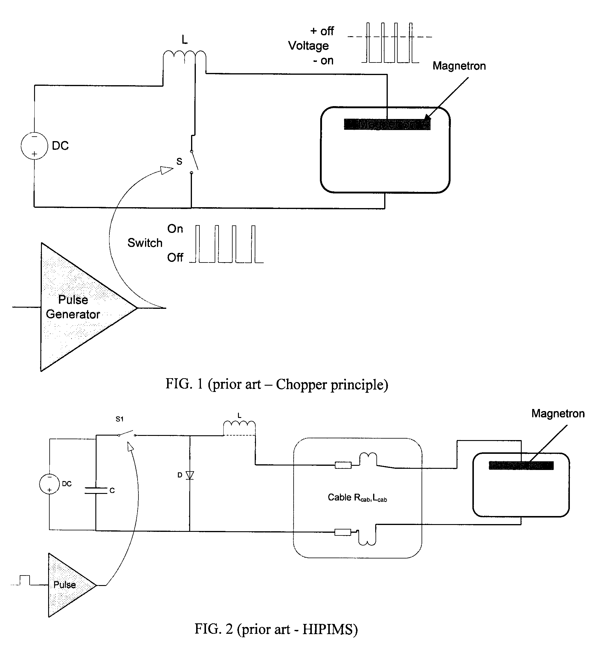
There are a number of disadvantages with the standard HIPIMS technique.
One disadvantage is that relatively large and expensive capacitors dimensioned for high stored energy and for substantially voltage other than the magnetron operation voltage are provided.
Another disadvantage is that the magnetron is operated in a mode close to constant voltage, in contrast to operating the magnetron in a constant current mode.
One other disadvantage is that there is a long starting time of the magnetron current pulse (5 to 100 μs), as seen in the experiment of FIG. 6.
Another disadvantage is that there is a long delay between the voltage pulse and the start of the current rise (2 to 20 μs).
This is not favorable for chopper operation, as a full peak discharge current should flow through the coil over the long plasma off period, causing high resistive losses in the coil.
Also the coil dimensions for the enormous stored energy are not practical.
The prior art literature of Helmersson, Christie, and Vl{hacek over (c)}ek show that one of the major drawbacks of HIPIMS is a relatively lower deposition rate per average input power.
The high discharge current values used in HIPIMS also create an increased risk of arcing.
Arcs are undesirable because the energy in the system discharges too rapidly.
Damage done by such hot spots to the surface of the target has been described as well as emission of droplets and particles.
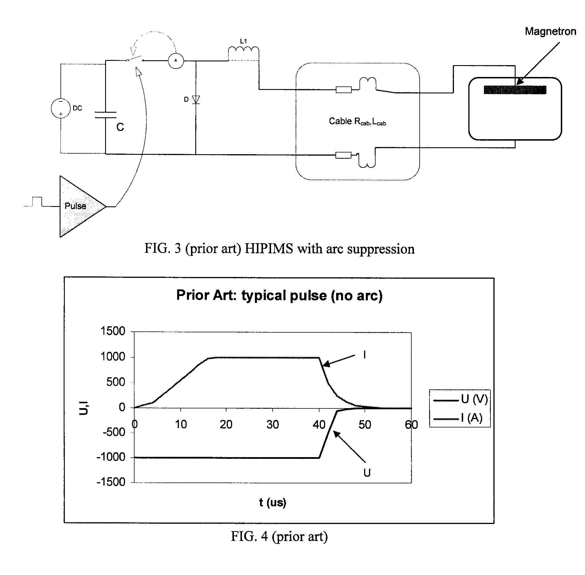
This results in a sharp increase of current, but the increase is limited in amplitude and rise by the serial impedance of Lcab, L1 and Rcab.
Nevertheless, the energy E stored in the cable and the coil may be relatively large.
Nevertheless, for processes sensitive to particles, such as semiconductor wafer processing, thin film heads, MEMS, and optical or magnetic data storage, the residual energy fed into an arc may be too large.
Droplets emitted from arcs during deposition may cause malfunction of some devices being produced on a silicon wafer or another substrate.
An even worse problem can be the accumulation of particles in the processing chamber, for example after installing a new target.
Such new targets often exhibit a much larger tendency to arcing than older, sputter-eroded targets.
The standard techniques used for arc suppression have a disadvantage of leaving too much energy available for an arc discharge after the arc suppression electronics reacted.

Method used


Image

  • Arc suppression and pulsing in high power impulse magnetron sputtering (hipims)
  • Arc suppression and pulsing in high power impulse magnetron sputtering (hipims)
  • Arc suppression and pulsing in high power impulse magnetron sputtering (hipims)

Examples


Embodiment Construction

[0042]Examples that incorporate one or more aspects of the present invention are described and illustrated in the drawings. These illustrated examples are not intended to be a limitation on the present invention. For example, one or more aspects of the present invention can be utilized in other embodiments and even other types of devices. Moreover, certain terminology is used herein for convenience only and is not to be taken as a limitation on the present invention. Still further, in the drawings, the same reference numerals are employed for designating the same elements.

[0043]In HIPIMS it is not commonly known to use fast switching with on-times below 10 μs. The example of FIG. 7 is designed based on measurements made at low frequencies (1 to 200 Hz) showing high rise times of current in μs, limiting shortest pulse on-times to about 10 μs and thus the maximum frequency to about 1 kHz, based on a duty cycle of 1%. The experiment in FIG. 6 showed a clear tendency to the possibility ...


PUM

PropertyMeasurementUnit
frequencyaaaaaaaaaa
frequencyaaaaaaaaaa
on-timeaaaaaaaaaa

Abstract

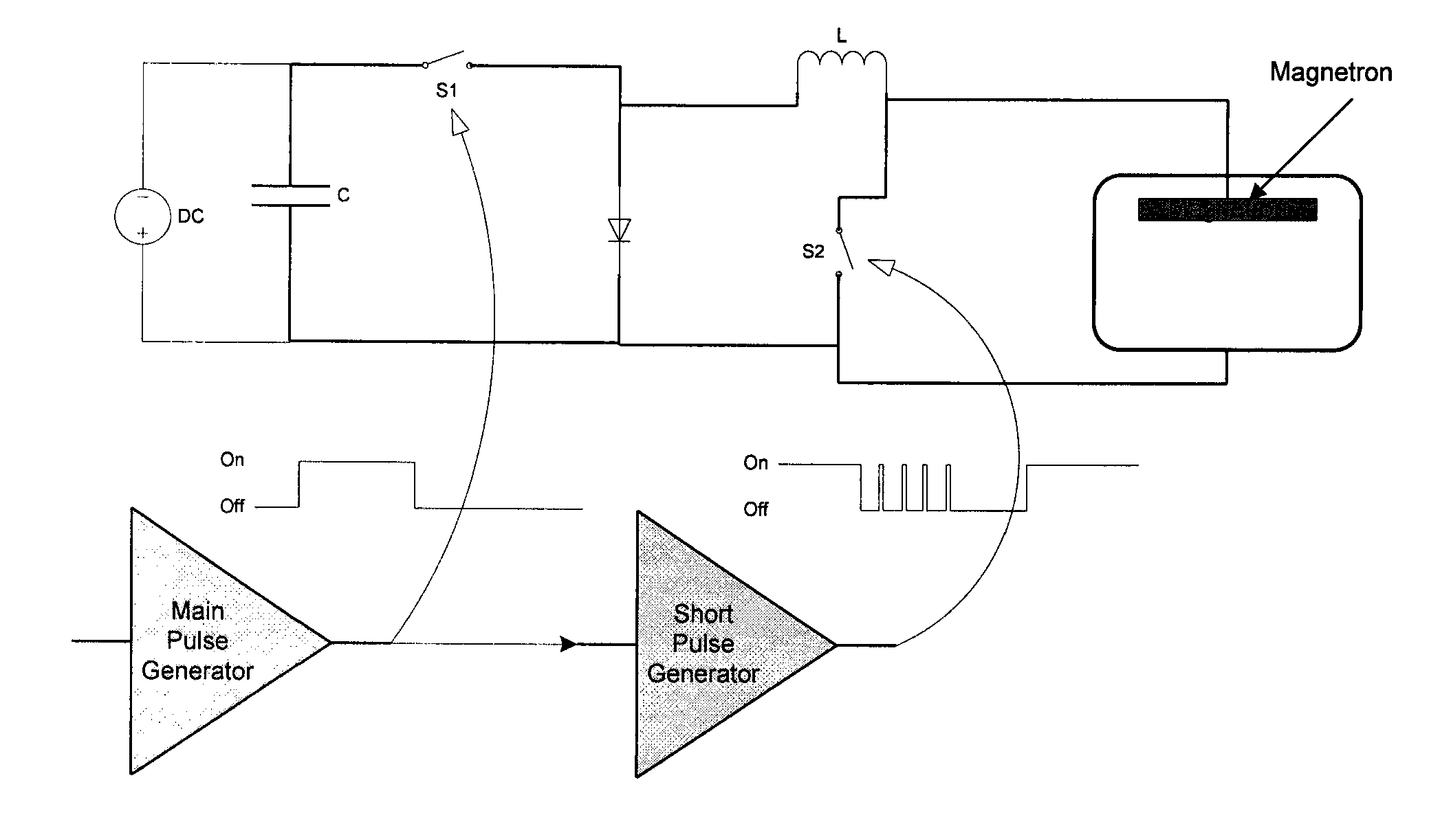
An apparatus for generating sputtering of a target to produce a coating on a substrate is provided. The apparatus comprises a magnetron including a cathode and an anode. A power supply is operably connected to the magnetron and at least one capacitor is operably connected to the power supply. The apparatus also includes an inductance operably connected to the at least one capacitor. A first switch and a second switch are also provided. The first switch operably connects the power supply to the magnetron to charge the magnetron and the first switch is configured to charge the magnetron according to a first pulse. The second switch is operably connected to discharge the magnetron. The second switch is configured to discharge the magnetron according to a second pulse.

Description

CROSS-REFERENCE TO RELATED APPLICATIONS[0001]This application claims the benefit of U.S. Provisional Application No. 60 / 869,566, filed Dec. 12, 2006, the entire disclosure of which is hereby incorporated herein by reference. This application also claims the benefit of U.S. Provisional Application No. 60 / 869,578, filed Dec. 12, 2006, the entire disclosure of which is hereby incorporated herein by reference. This application also claims the benefit of U.S. Provisional Application No. 60 / 869,912, filed Dec. 14, 2006, the entire disclosure of which is hereby incorporated herein by reference.BACKGROUND OF THE INVENTION[0002]The present invention relates generally to generating sputtering to produce a coating on a substrate, more particularly, to high power impulse magnetron sputtering (HIPIMS).[0003]Sputtering is a physical process whereby atoms in a solid target material are ejected into the gas phase due to bombardment of the material by energetic ions. The process of sputtering is com...

Claims


Application Information

Patent Timeline
Patent Type & Authority Applications(United States)
IPC IPC(8): C23C14/35
CPCH01J37/3444H01J37/3467C23C14/35C23C14/3485C23C14/345H01J37/3408H01J37/32944H01L21/20H01L21/02631H01J37/32045H01J37/32064
Inventor KADLEC, STANISLAVWEICHART, JURGEN
Owner EVATEC
Why Eureka
Try Eureka