[0011]In view of the foregoing, embodiments of the present invention advantageously provide a piezoelectric planar composite apparatus including piezoelectric material such as, for example, PZT or PZT fibers, which can be embedded, aligned, and mechanically and electrically connected to form a durable sensor based on piezoelectric and / or other similar technologies. According to embodiments of the present invention, the piezoelectric planar composite apparatus includes a plurality of
layers of insulating material which carry electrode interconnect conductors electrically interconnected to electrodes which are in turn in electrical communication with the piezoelectric material to produce electrical signals in response to mechanical inputs to thereby provide for monitoring various health-related parameters such as, for example, strain levels, stress, temperature, pressure, or vibration level of a structure to be monitored which can be distributed in arbitrary directions and which can vary over time. Embodiments of the present invention uniquely utilize bonding materials, both within the structure of the apparatus and to connect the apparatus to the structure to be monitored, that are capable of withstanding
high pressure and high temperature composite
processing and operation such as, for example, that associated with carbon and
carbon fiber composite lamination. Particularly, embodiments of the present invention can be formed by employing a process of layering and attaching
ceramic piezoelectric material, electrode interconnect conducting carrying
layers, or others to form two-dimensional and three-dimensional structures which include electrical conductors and connections and / or switchology to form arbitrarily complex electrode patterns and which allow the
piezoelectric composite apparatus to fit in arbitrarily small spaces, i.e., as small as 1 / 100th or 1 / 1000th of the space conventionally required.
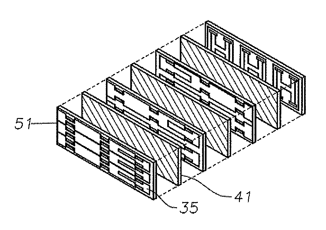
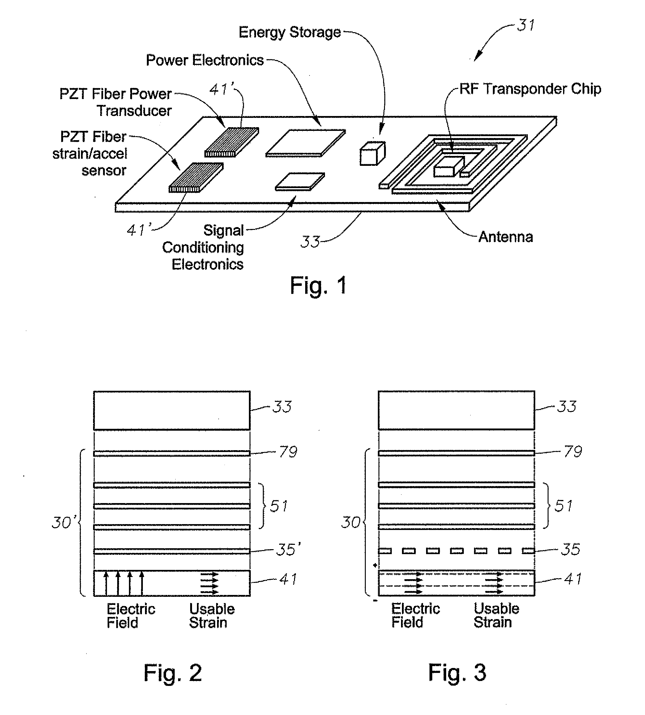
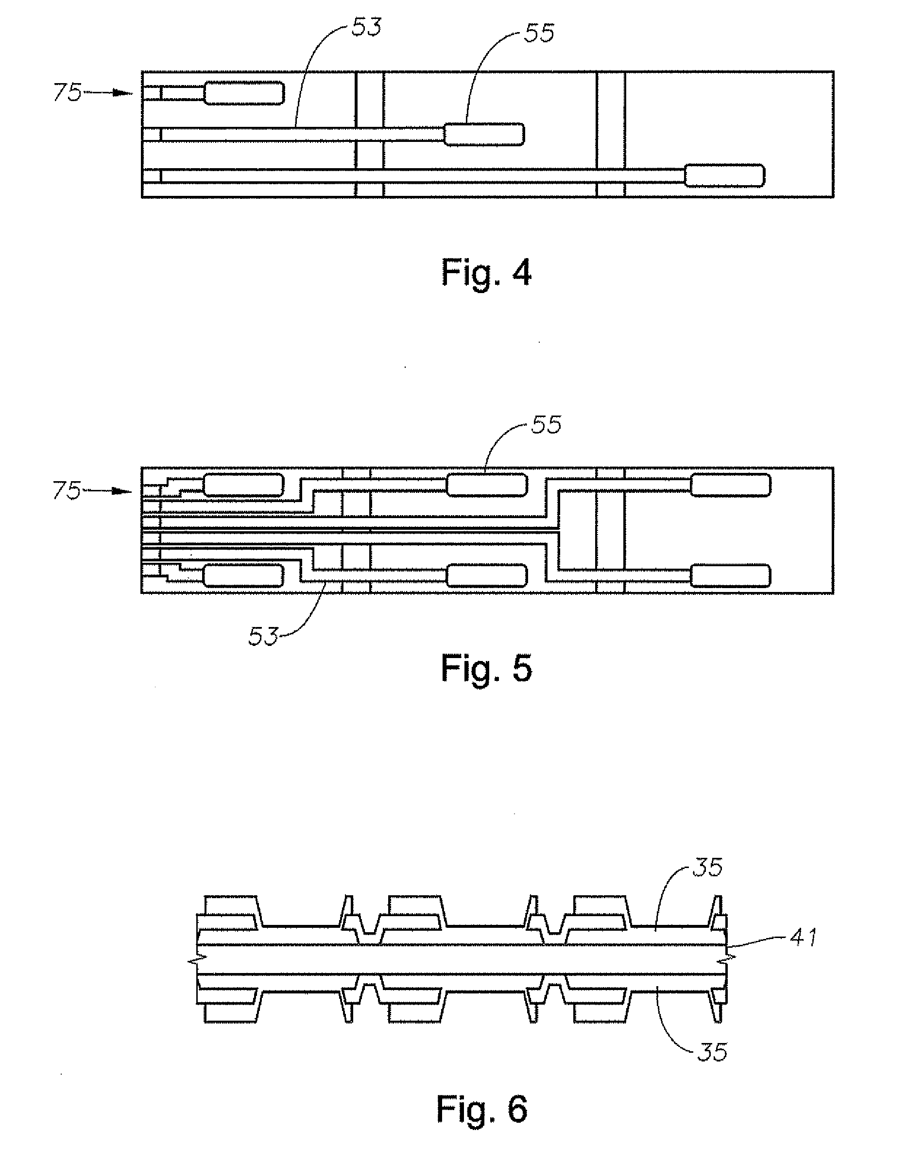
[0012]More specifically, according to an embodiment of the present invention, a piezoelectric planar composite apparatus includes a piezoelectric electric material layer, a plurality of electrodes positioned in electrical contact with the piezoelectric material layer, and a plurality of sets of electrode interconnect conductors each positioned in electrical contact with a different subset of the plurality of electrodes and positioned to form a plurality of complementary electrode patterns. Each of the plurality of complementary electrode patterns is positioned to form an electric field having an electric field axis oriented along a different physical axis from that of an electric field formed by at least one other of the complementary electrode patterns. Advantageously, this allows user selection of a different electric field axis dependent upon which complementary electrode pattern is selected. According to one embodiment, the sets of interconnect conductors are in the same plane and provide for establishing an N×N electrode matrix. According to another embodiment, sets of electrode interconnect conductors are distributed over a plurality of electrode interconnect conductor carrying layers each carrying a different one of the plurality of sets of electrode interconnect conductors.
[0015]Embodiments of the apparatus allow for positioning of the apparatus in arbitrarily small locations on or adjacent a structure and in arbitrary orientations. Particularly, embodiments of the piezoelectric composite apparatus can allow the user to electrically switch off and on particular electrodes to form a plurality of separately distinct complementary electrode patterns so that the electric field generated by the piezoelectric material is substantially aligned with the presently existing axis of
usable strain without physically changing the position of the piezoelectric apparatus. Embodiments of the apparatus alternatively can provide the ability to select from a plurality of preselected distinct complementary electrode patterns rather than individual electrodes forming the electrode patterns to provide for manipulation of the electric
field orientation.
[0016]In order to connect to or be positioned or laminated within the structure to be monitored, embodiments of the apparatus can include an apparatus interconnect layer positioned to connect the apparatus with the structure to be monitored. When the apparatus is to be, for example, interlaminated within the structure to be monitored during formation thereof and the structure to be monitored during such formation requires very high temperatures and pressures such as that required by a carbon
fiber structure or carbon
epoxy, the interconnect layer can include a very high temperature resin such as an addition-type
polyimide resin which includes characteristic capabilities to enable the piezoelectric planar composite apparatus to withstand a pressure of at least approximately 100 PSI and temperature of at least approximately 190° C. for approximately six hours without failure during the interlamination within the
composite structure during formation thereof.
[0017]Embodiments of the present invention also include methods of forming the piezoelectric composite apparatus. According to an embodiment of a method, blocks of fired piezoelectric material, e.g., PZT, are
cut into slices of thin wafers. These wafers are bonded together in a stack using a high temperature film
adhesive or resin. The stack is sliced again in the
perpendicular direction creating composite wafers of PZT fibers and resin. These composite wafers are then laminated directly to or between a
dielectric material such as
Kapton® using a liquid high temperature resin. Electrodes on the
Kapton® or directly on the PZT fibers can create an electric field in the plane of the assembled, composite
wafer to align the major piezoelectric poling axis with the direction of strain to be measured. According to an embodiment of the method, multiple layers of
Kapton® carrying electrode interconnect conductors connecting to different combinations of electrodes can be stacked on either or both sides of the PZT fibers. Various combinations of the electrodes can be connected to a
data acquisition system to measure output charge that is related to
voltage and in this example, strain. Advantageously, this manufacturing and installation process can produce sensors that can be embedded or surface bonded to composite structures and that are significantly stronger, operate at higher temperatures, and facilitate higher output when compared with similar existing sensors.

