Heat sink

a heat sink and heat sink technology, applied in the field of heat sinks, can solve the problems of low cooling performance relative to cost, high manufacturing cost of heat sinks, and inability to achieve high heat dissipation performance of heat sinks, so as to reduce weight, and improve heat dissipation performance

Inactive Publication Date: 2008-06-19
FUJI ELECTRIC SYST CO LTD
View PDF28 Cites 29 Cited by
  • Summary
  • Abstract
  • Description
  • Claims
  • Application Information

AI Technical Summary

Benefits of technology

[0012]The present invention has been developed in view of the above described circumstances and provides a heat sink that can make the velocity of air between fins uniform to improve heat dissipation performance, thereby realizing a reduction in weight and achieving high cost performance.
[0016]According to the present invention, since the distal ends of the fins in the flowing direction of cooling air are arranged so that the distal ends of the fins which are not located in the vicinity of the cooling fan are located downstream of the distal ends of the fins located in the vicinity of the cooling fan, the air-velocity distribution between the fins can be made uniform, so that cooling efficiency for the fins can be improved as a whole, and the heat sink having high cooling performance per unit weight can be realized.
[0017]Further, since the distal ends of the fins on the advance side in the rotational direction of the cooling fan are located downstream of the distal ends of the fins on the delay side in the rotational direction of the cooling fan, the air velocity on the delay side in the rotational direction of the cooling fan can be increased, making the air-velocity distribution between the fins more uniform, so that the cooing performance of the heat sink per unit weight can be further improved.

Problems solved by technology

Thus, due to unevenness in air velocity, the conventional heat sinks cannot always achieve high heat dissipation performance although they have large surface areas.
Moreover, in a case where the heat sinks are manufactured by aluminum die-casting, they are mass-produced using dies, and hence the manufacturing cost of the heat sinks is determined mainly by the weight of an aluminum material.
Thus, the conventional heat sinks have the problem that cooling performance is not high relative to the cost if fins having the same lengths are disposed on the base surface.

Method used


Image

  • Heat sink
  • Heat sink
  • Heat sink

Examples


first embodiment

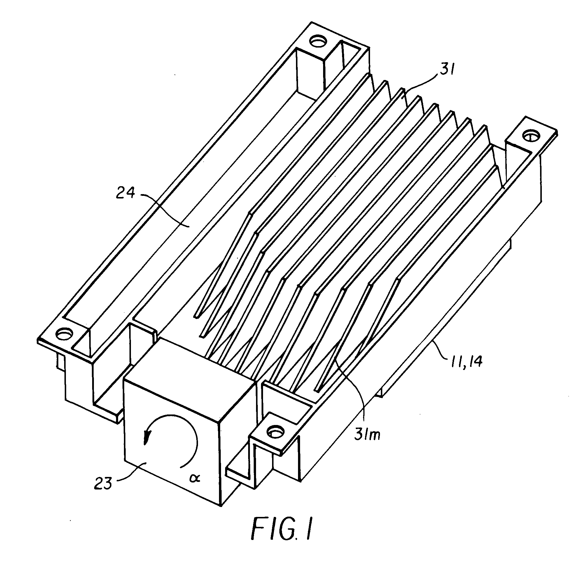
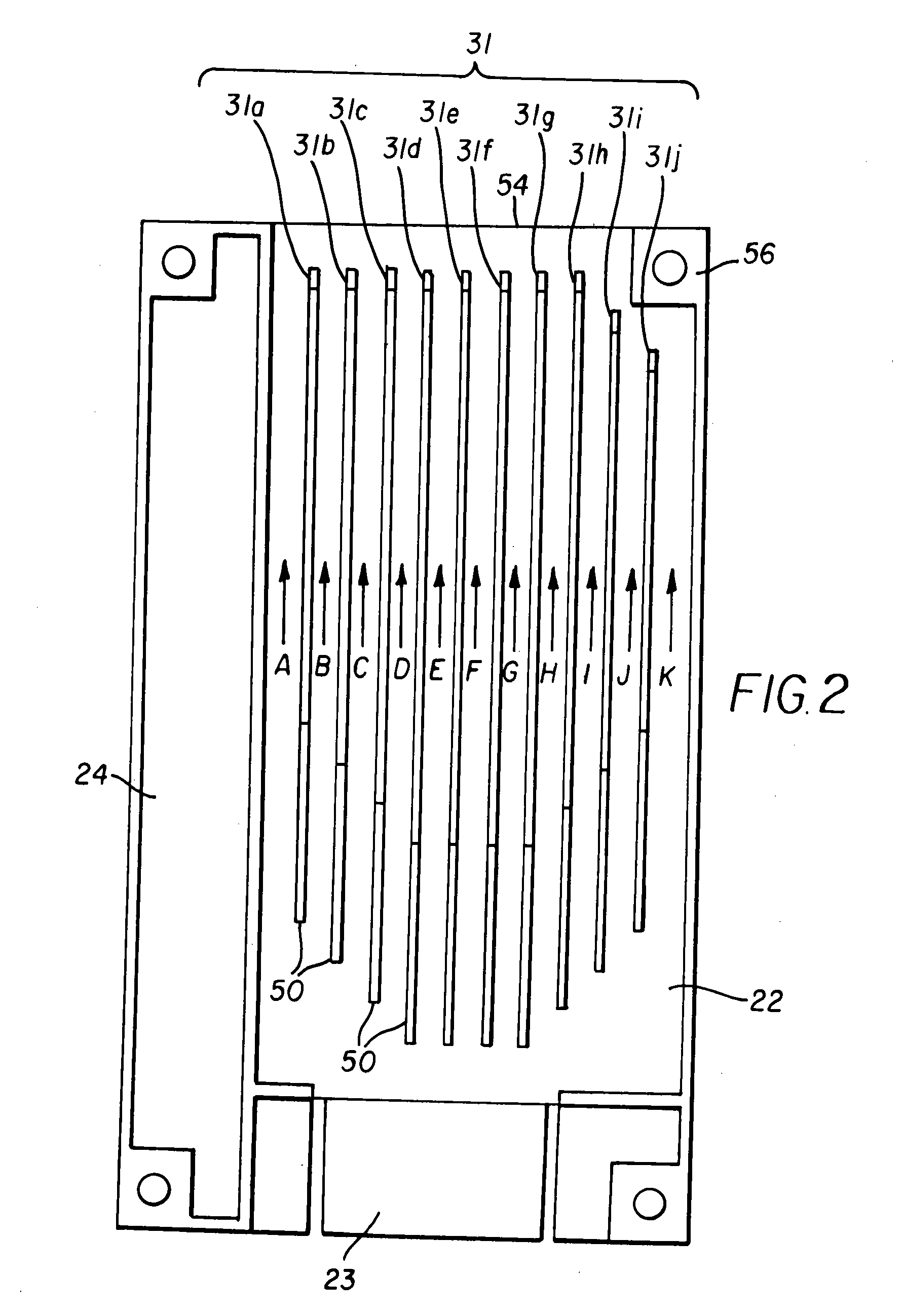
[0037]FIG. 3 is a diagram showing an example of the air-velocity distribution between the fins in the heat sink in a case where the air-velocity distribution of cooling air in flow paths A to K indicated by arrows between the fins 31a to 31j appearing in FIG. 2 is measured. As shown in FIG. 3, as compared with the air-velocity distribution in the conventional art illustrated in FIG. 12, the air velocity can be made more uniform, and the average air velocity can be made higher.

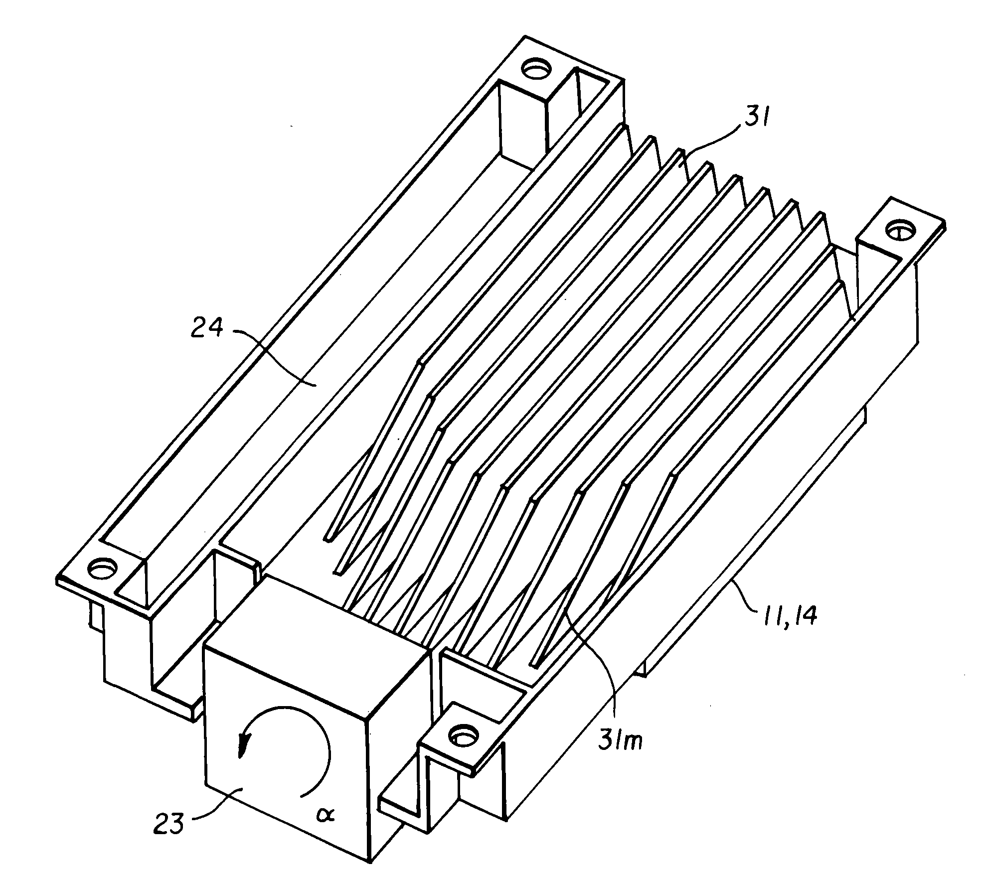
[0038]One of the reasons why the air velocity can be made more uniform is that pressure loss is reduced because the fins 31a to 31c and 31h to 31j, which are not located in the vicinity of the cooling fan 23, are made shorter, and their distal ends 50 are located further downstream or away from the inflow end face 52. Another reason why the air velocity can be made uniform is that the fins 31 are provided with the slopes 31m so that the height of each fin 31 from the base surface gradually increases from the u...

second embodiment

[0042]In the second embodiment illustrated in FIGS. 4 and 5, fins 41 located on the delay side in the rotational direction of the cooling fan 23 (right side as viewed in FIG. 5) (as indicated by the arrow α) are formed to be shorter than fins 41 located on the advance side in the rotational direction of the cooling fan 23 (left side as viewed in FIG. 5), and distal ends of fins 41f to 41j on the delay side in the rotational direction of the cooling fan 23 are located downstream of distal ends of fins 41a to 41e on the advance side in the rotational direction of the cooling fan 23.

[0043]FIG. 6 is a diagram showing an example of the air-velocity distribution between the fins in the heat sink according to the second embodiment in a case where the air-velocity distribution of cooling air in flow paths A to K indicated by arrows between the fins 41a to 41j appearing in FIG. 5 is measured. As shown in FIG. 5, as compared with the air-velocity distribution in FIG. 3, the air velocity in th...


PUM


Abstract

A heat sink is provided that makes air velocity between cooling fins uniform in order to improve heat dissipation performance, thereby realizing a reduction in weight and achieving high cost performance. Distal ends of fins disposed substantially in front of a cooling fan are located on the uppermost stream side in the flowing direction of cooling air, and distal ends of fins on both sides in the width direction of the heat sink are located on the lowermost stream side. Each of the fins is preferably provided with a slope so that the height of the fin gradually increases from the distal end thereof in a direction from the upstream side to the downstream side in the flowing direction of cooling air.

Description

BACKGROUND[0001]The present invention relates to a heat sink that is air-cooled with forced air from a cooling fan, and more particularly to a heat sink for an inverter unit that converts alternating-current power supplied from a commercial power supply or the like into alternating-current power with a predetermined frequency and voltage and feeds the resultant power to an electric motor or the like.[0002]FIG. 7 is a diagram showing a typical circuit configuration of an inverter unit of the above-mentioned type. The inverter unit 10 in FIG. 7 includes a converter 11 that rectifies alternating-current voltage supplied from a commercial power supply or the like via a terminal 19a of a terminal block 19 (see FIG. 8), an electrolytic capacitor 12 that smoothes the rectified voltage, an inverter 14 that converts the smoothed voltage across the electrolytic capacitor 12 into alternating-current voltage with a desired frequency that is output via a terminal 19b of the terminal block 19, a ...

Claims


Application Information

Patent Timeline
Patent Type & Authority Applications(United States)
IPC IPC(8): H05K7/20
CPCH05K7/20918H01L2924/0002H01L2924/00
Inventor YAMAMOTO, TSUTOMUHATOZAKI, YOSHIHISA
Owner FUJI ELECTRIC SYST CO LTD
Why Eureka
Try Eureka