
Transmitter built-in production line testing utilizing digital gain calibration

a technology of digital gain and production line, applied in the field of data communication, can solve the problems of high noise floor (also referred to as error vector magnitude or evm), high cost, and large volume of test equipment used, and achieve the effect of simplifying the implementation

Active Publication Date: 2008-06-19
TEXAS INSTR INC
View PDF2 Cites 68 Cited by
  • Summary
  • Abstract
  • Description
  • Claims
  • Application Information

AI Technical Summary

Benefits of technology

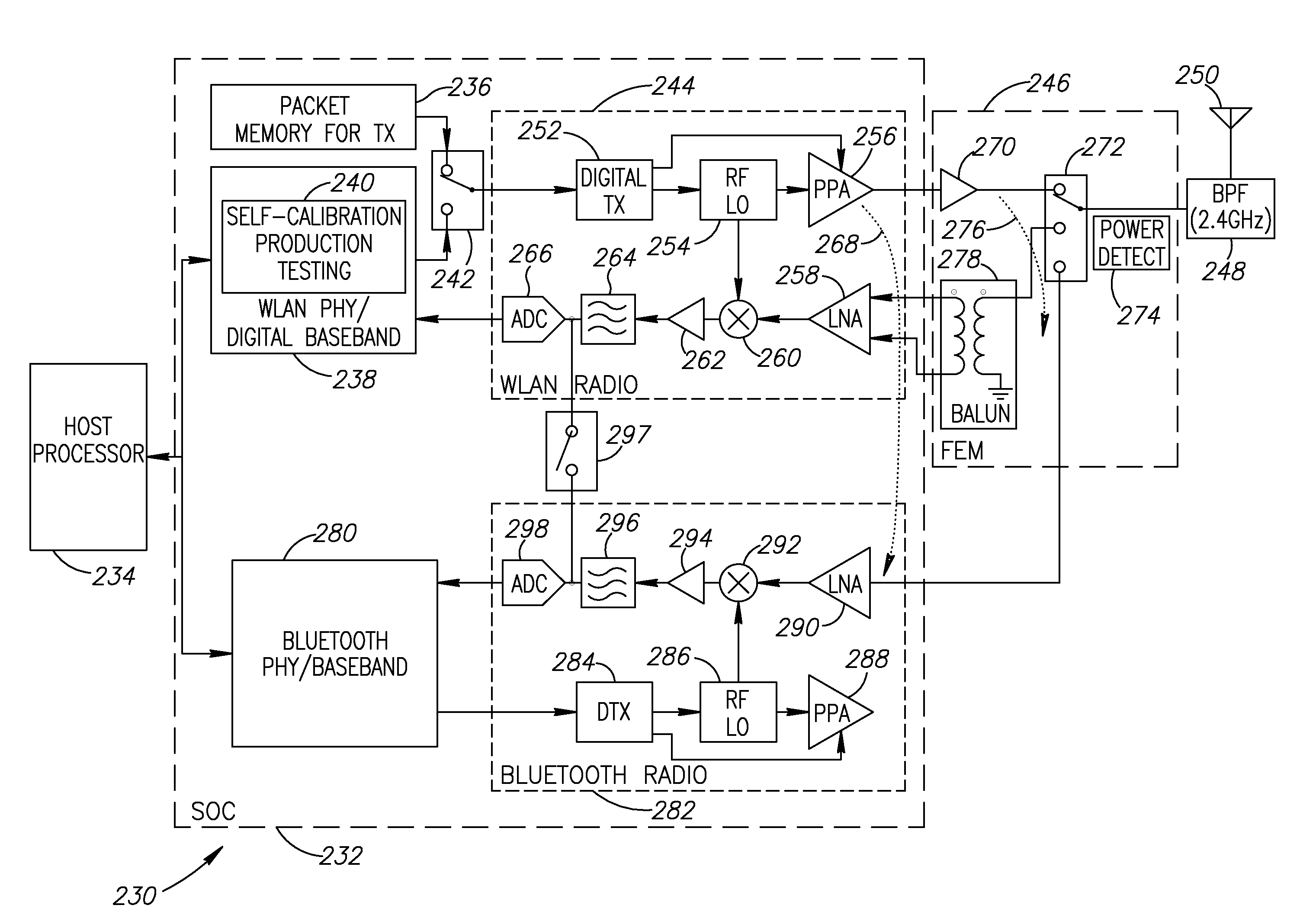
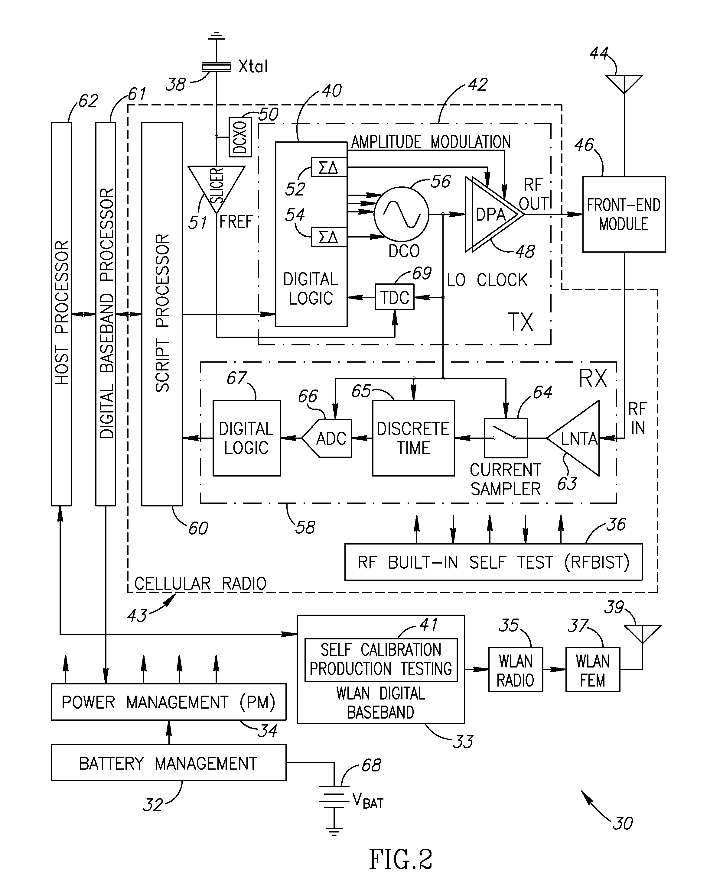
The present invention is a novel and useful self-calibration based production line testing mechanism for radios that use identical IF frequencies for transmit and receive. The mechanism utilizes built-in closed loop measurements in the radio to calibrate the digital gain of an external power amplifier and the power detector. The calibration process involves performing closed loop calibration of the input signal to yield a maximum power amplifier output power level that meets predetermined transmission requirements. The calibration is done at the end of the fabrication and testing process of the device, reducing testing costs and the need for separate calibration equipment. The invention provides a method and apparatus for calibrating an external power amplifier in a radio that incorporates a pre-power amplifier and a receiver capable of operating simultaneously. The calibration process involves injecting samples into the transmit path, downconverting and demodulating a receive signal leaked through the external power amplifier, increasing the transmit power of the amplifier until a maximum power amplifier output power level is reached that meets the predetermined transmission requirements, and adjusting the maximum amplifier codeword to meet the requirements. The invention simplifies the calibration process, reduces testing costs, and improves the accuracy of the calibration.

Problems solved by technology

At high transmitted power levels, however, the noise floor (also referred to as the Error Vector Magnitude or EVM) contribution from the power amplifier (PA) becomes high as well.
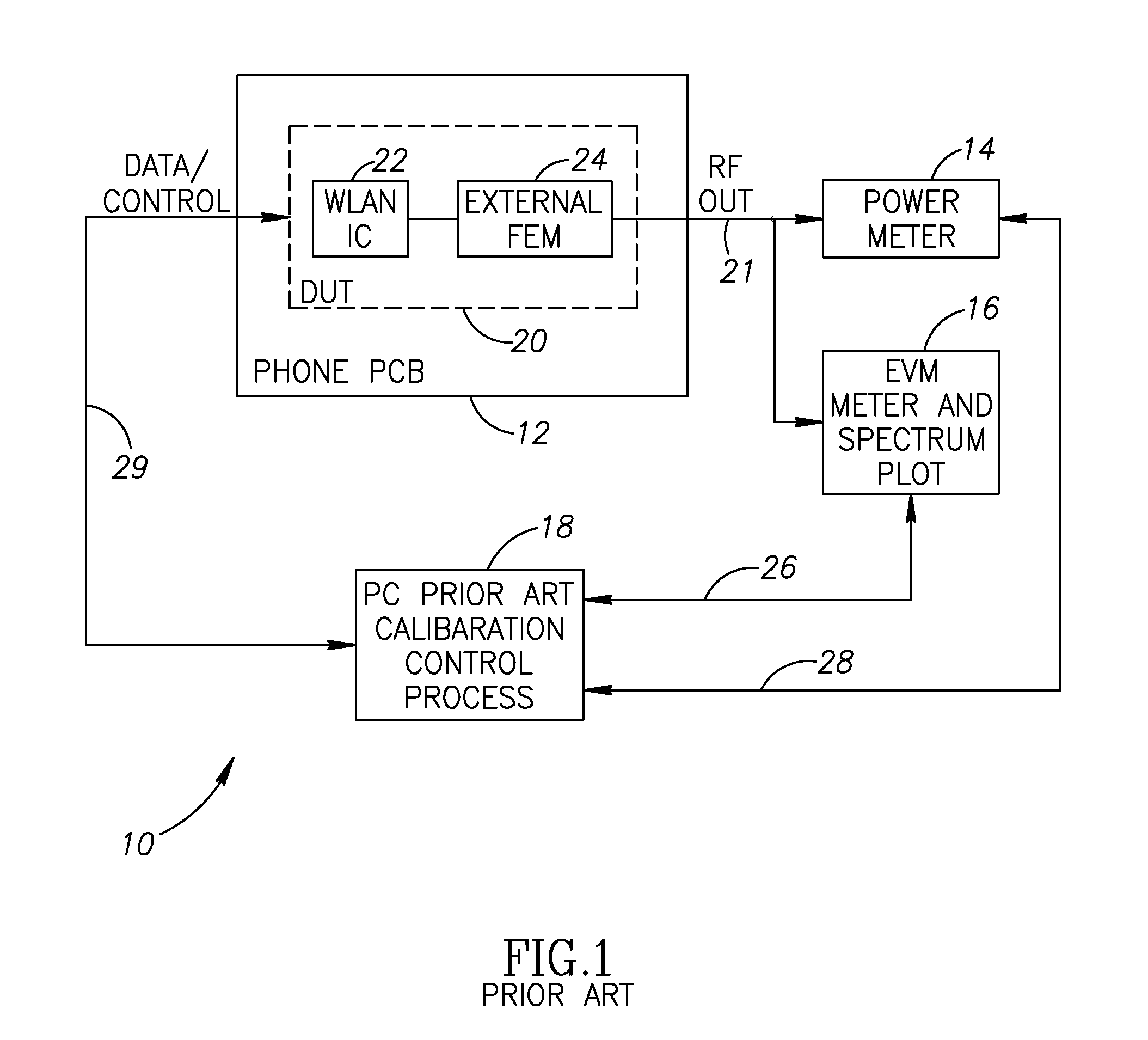
The test equipment used is typically bulky in size, costly and requires routine maintenance and calibration of its own.
The testing is performed on the cell phone production line whereby the test equipment communicates extensively with the cell phone SoC, PCB assemblies, etc. which consumes a considerable amount of time thus making this testing process very costly.

Method used


Image

  • Transmitter built-in production line testing utilizing digital gain calibration
  • Transmitter built-in production line testing utilizing digital gain calibration
  • Transmitter built-in production line testing utilizing digital gain calibration

Examples


Embodiment Construction

Notation Used Throughout

[0030]The following notation is used throughout this document.

TermDefinitionACAlternating CurrentACWAmplitude Control WordADCAnalog to Digital ConverterADPLLAll Digital Phase Locked LoopAMAmplitude ModulationASICApplication Specific Integrated CircuitAVIAudio Video InterfaceBISTBuilt-In Self TestBMPWindows BitmapBPFBand Pass FilterBPSKBinary Phase Shift KeyingCMOSComplementary Metal Oxide SemiconductorCPUCentral Processing UnitCWContinuous WaveDBBDigital BasebandDCDirect CurrentDCODigitally Controlled OscillatorDCXODigitally Controlled Crystal OscillatorDPADigitally Controlled Power AmplifierDRACDigital to RF Amplitude ConversionDRPDigital RF Processor or Digital Radio ProcessorDSLDigital Subscriber LineDSPDigital Signal ProcessorDUTDevice Under TestEDGEEnhanced Data Rates for GSM EvolutionEDREnhanced Data RateEPROMErasable Programmable Read Only MemoryEVMError Vector MagnitudeFCWFrequency Command WordFEMFront End ModuleFFTFast Fourier TransformFIBFocused Ion...


PUM


Abstract

A novel and useful self-calibration based production line testing mechanism utilizing built-in closed loop measurements in the radio to calibrate the output power of an external power amplifier coupled to a SoC radio. The mechanism is applicable during production line testing and calibration which is performed on each SoC and associated external power amplifier after assembly at the target PCB of the final product. The mechanism calibrates the TX output power in three phases based on loopback EVM measurements. In a first phase, the PPA in the radio (SoC) is calibrated and gain versus output power is stored in a gain table in on-chip NVS. In a second phase, the maximum PPA TX power is determined using closed loop EVM measurements. The external PA is calibrated in a third phase and the maximum PA power is determined. During this third phase, the maximum power of the device is calculated, compared to the requirements of the particular standard and a pass / fail determination is thereby made.

Description

REFERENCE TO PRIORITY APPLICATION[0001]This application claims priority to U.S. Provisional Application Ser. No. 60 / 870,763, filed Dec. 19, 2006, entitled “Transmitter Built-In Production Line Testing,” incorporated herein by reference in its entirety.FIELD OF THE INVENTION[0002]The present invention relates to the field of data communications and more particularly relates to a built-in production line testing mechanism that utilizes self-calibration techniques to calibrate the digital gain of an external power amplifier that significantly reduces the cost of production testing radio frequency (RF) transmitters.BACKGROUND OF THE INVENTION[0003]Wireless communication transmitters that are used to carry high linear modulation formatted signals, such as Wireless LAN (WLAN) signals, are often required to transmit relatively high transmit power. At high transmitted power levels, however, the noise floor (also referred to as the Error Vector Magnitude or EVM) contribution from the power a...

Claims


Application Information

Patent Timeline
Patent Type & Authority Applications(United States)
IPC IPC(8): H04B17/00H04B1/40
CPCH04B17/13
Inventor TSFATI, YOSSITAL, NIRBAUM, AVISHERMAN, ITAY
Owner TEXAS INSTR INC
Learn More