Apparatus for measuring the characteristics of an optical fiber
- Summary
- Abstract
- Description
- Claims
- Application Information
AI Technical Summary
Benefits of technology
Problems solved by technology
Method used
Image
Examples
first embodiment
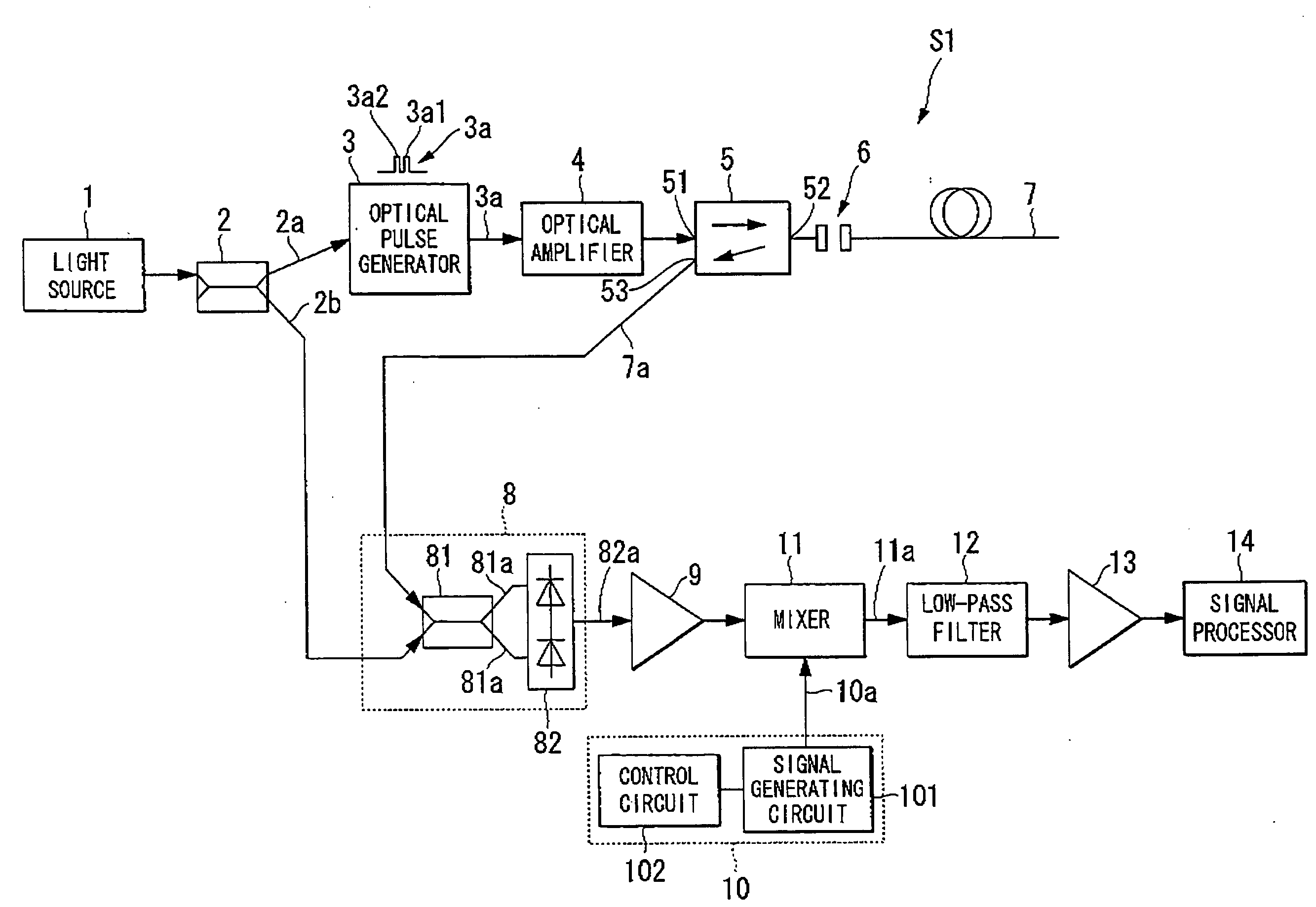
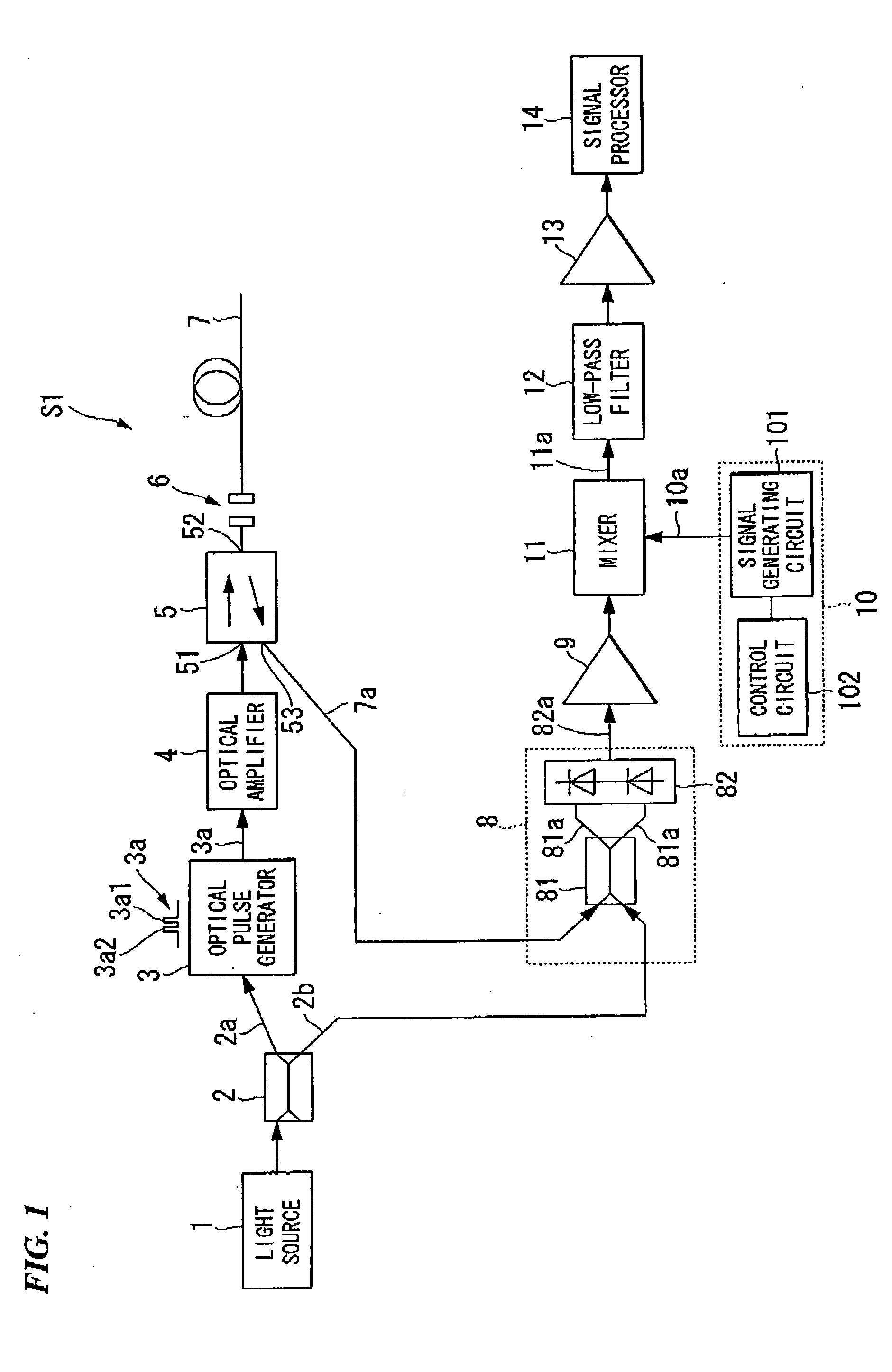
[0043]FIG. 1 is a block diagram illustrating a configuration of an apparatus S1 for measuring the characteristics of an optical fiber in accordance with this first embodiment of the present invention. The apparatus S1 for measuring the characteristics of an optical fiber may include a light source 1, a branch coupler 2, an optical pulse generator 3, an optical amplifier 4, an optical directional coupler 5, an optical connector 6, an optical fiber 7, a balanced light receiving circuit 8, a first amplifier 9, a signal generator 10, a mixer 11, a low-pass filter 12, a second amplifier 13, and a signal processing unit 14. The optical fiber 7 is subjected to measurement by the apparatus S1.
[0044]The light source 1 is configured to emit a coherent light 1a having a narrow line-width and a frequency f0. The light source 1 can be realized by a 1.55 μm-band multiple quantum well distributed feedback (MQW-DFB) semiconductor laser.
[0045]The branch coupler 2 can be configured to divide the cohe...
second embodiment
[0112]A second embodiment of the present invention will be described. The second embodiment provides an apparatus S2 for measuring the characteristics of an optical fiber. The apparatus S2 is different from the apparatus S1 described above. The following descriptions will focus on the difference of the apparatus S2 from the apparatus S1 to avoid duplicate descriptions thereof.
[0113]FIG. 10 is a block diagram illustrating a configuration of an apparatus for measuring the characteristics of an optical fiber in accordance with the second embodiment of the present invention. The apparatus S2 for measuring the characteristics of an optical fiber may include a light source 1, a branch coupler 2, an optical pulse generator 3, an optical amplifier 4, an optical directional coupler 5, an optical connector 6, an optical fiber 7, a balanced light receiving circuit 8, a first amplifier 9, a signal generator 10, a mixer 11, a low-pass filter 12, a second amplifier 13, a signal processing unit 14...
third embodiment
[0120]A third embodiment of the present invention will be described. The third embodiment provides an apparatus S3 for measuring the characteristics of an optical fiber. The apparatus S3 is different from the apparatus S1 described above. The following descriptions will focus on the difference of the apparatus S3 from the apparatus S1 to avoid duplicate descriptions thereof. The apparatus S3 for measuring the characteristics of an optical fiber may include a light source 1, a branch coupler 2, an optical pulse generator 3, an optical amplifier 4, an optical directional coupler 5, an optical connector 6, an optical fiber 7, a balanced light receiving circuit 8, a first amplifier 9, a signal generator 10, a mixer 11, a low-pass filter 12, a second amplifier 13, a signal processing unit 14, and an ASE-light removing optical switch 30.
[0121]The ASE-light removing optical switch 30 is disposed between the optical amplifier 4 and the optical directional couplet 5. The ASE-light removing o...
PUM
 Abstract
Description
Claims
Application Information
 - R&D
- Intellectual Property
- Life Sciences
- Materials
- Tech Scout
- Unparalleled Data Quality
- Higher Quality Content
- 60% Fewer Hallucinations
Browse by: Latest US Patents, China's latest patents, Technical Efficacy Thesaurus, Application Domain, Technology Topic, Popular Technical Reports.
© 2025 PatSnap. All rights reserved.Legal|Privacy policy|Modern Slavery Act Transparency Statement|Sitemap|About US| Contact US: help@patsnap.com


