Recycling of large-size photomask substrate

a photomask and substrate technology, applied in the field of large-scale photomask substrate recycling, to achieve the effects of improving the production yield of panels, reducing the burden of exposure correction, and improving the accuracy of exposure correction

Active Publication Date: 2008-06-19
SHIN ETSU CHEM IND CO LTD
View PDF8 Cites 5 Cited by
  • Summary
  • Abstract
  • Description
  • Claims
  • Application Information

AI Technical Summary

Benefits of technology

[0035]When a large-size photomask substrate regenerated from a used large-size glass substrate by the recycling method of the invention is used in the exposure process, the exposure accuracy, especially registration accuracy and resolution are improved. This not only enables exposure of a high definition large-size panel, but also reduces the burden of exposure correction and improves the production yield of panels. An exposure apparatus of the so-called proximity type (i.e., proximity aligner) which is used only on the color filter side in the prior art can be used on the TFT array side to which a projection exposure apparatus (i.e., projection aligner) is assigned in the prior art. Another potential advantage on the color filter side is that an exposure apparatus of the proximity type is adaptable to the black matrix and photo-spacer as well as RGB.
[0036]In the manufacture of a large-size photomask substrate according to the invention, there is obtained a large-size photomask substrate which has such an arcuate shape in cross section that the surface to be opposed to the mother glass is concave when held vertically. When only conventional repolishing is employed in recycling such a photomask substrate, the shape of a used large-size photomask substrate prior to recycling is left or at least the shape cannot be changed to any desired one. On use of sand blasting, a large-size photomask substrate of the desired shape complying with the required large-size photomask substrate can be efficiently produced at a reduced quantity of material removed, independent of the shape of a used large-size photomask substrate prior to recycling.
[0037]When exposure is carried out using a regenerated photomask substrate obtained by the recycling method of the invention, the proximity gap is made small and uniform (minimized variation) so that control of the proximity gap is facilitated. As a result, the number of products by exposure can be increased and the large-size glass substrate allows for efficient exposure. In addition, the number of substrate recycles can be increased and the cost of substrates is eventually reduced.
[0038]When projection exposure is carried out using a regenerated photomask substrate formed from the regenerated large-size glass substrate stock according to the invention, the burden of correction of a shifting of an optical axis by substrate deflection is reduced. A need for correction of the proximity gap on the exposure apparatus side is substantially eliminated.

Problems solved by technology

When only conventional repolishing is employed in recycling such a photomask substrate, the shape of a used large-size photomask substrate prior to recycling is left or at least the shape cannot be changed to any desired one.

Method used


Image

  • Recycling of large-size photomask substrate
  • Recycling of large-size photomask substrate
  • Recycling of large-size photomask substrate

Examples


example 1

[0095]A used large-size photomask substrate with a chromium light-shielding film had a size of 330 mm×450 mm (diagonal length approx. 558 mm) and a thickness of 5.0 mm. It was immersed in a remover solution of 13.7 wt % of ammonium cerium(IV) nitrate (Ce(NO3)4.2NH4NO3) and 3.3 wt % of perchloric acid in water. The chromium light-shielding film was thus removed, yielding a glass substrate stock.

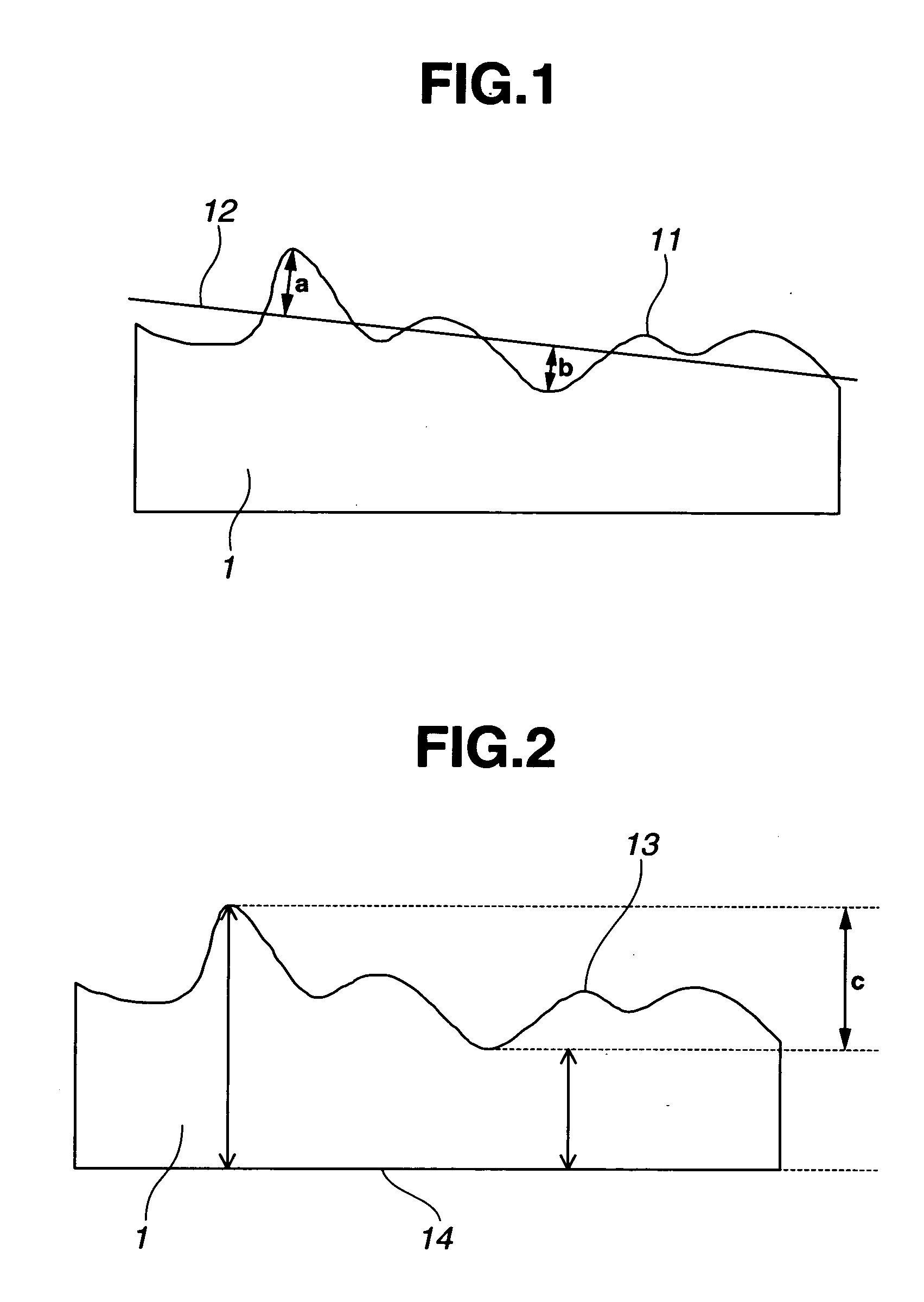
[0096]The substrate stock was measured for accuracy in the vertical attitude, finding a front surface flatness of 8 μm (surface flatness / diagonal length=1.43×10⁻⁵), a back surface flatness of 8 μm, and a parallelism of 8 μm. It was of a shape having a raised center portion relative to the least square plane.

[0097]Then, a deflection of the substrate stock by its own weight when held horizontally was calculated using material strength and the support position of a substrate when held horizontally. A substrate deformation and platen accuracy distortion were previously inspected from a quantity of...

example 2

[0106]The procedure of Example 1 was repeated except that the used large-size photomask substrate had a size of 520 mm×800 mm (diagonal length approx. 954 mm) and a thickness of 10.0 mm.

[0107]The proximity gap was measured over substantially the entire region using a laser displacement meter. The measurements of proximity gap included a maximum value of 58 μm and a minimum value of 47 μm, over the entire region excluding the peripheral regions extending 4 cm from the sides, with a gap error of 11 μm.

example 3

[0108]The procedure of Example 1 was repeated except that the used large-size photomask substrate had a size of 850 mm×1,200 mm (diagonal length approx. 1,471 mm) and a thickness of 10.0 mm.

[0109]The proximity gap was measured over substantially the entire region using a laser displacement meter. The measurements of proximity gap included a maximum value of 59 μm and a minimum value of 47 μm, over the entire region excluding the peripheral regions extending 4 cm from the sides, with a gap error of 12 μm.


PUM

PropertyMeasurementUnit
thicknessaaaaaaaaaa
thicknessaaaaaaaaaa
sizeaaaaaaaaaa

Abstract

A used large-size photomask substrate having a patterned light-shielding film is recycled by (i) removing the light-shielding film from the used substrate to provide a photomask-forming glass substrate stock, (ii) resurfacing the glass substrate stock by sand blasting, (iii) repolishing the resurfaced glass substrate stock to yield a regenerated glass substrate stock, (iv) applying a light-shielding film onto the regenerated glass substrate stock to yield a regenerated photomask-forming blank, and (v) processing the light-shielding film of the blank into a pattern corresponding to the desired exposure of a mother glass, yielding a regenerated photomask substrate.

Description

CROSS-REFERENCE TO RELATED APPLICATION[0001]This non-provisional application claims priority under 35 U.S.C. §119(a) on Patent Application No. 2006-338344 filed in Japan on Dec. 15, 2006, the entire contents of which are hereby incorporated by reference.TECHNICAL FIELD[0002]This invention relates to a method of recycling large-size photomask substrates for use as photomask substrates on the array side or color filter side of TFT liquid crystal panels.BACKGROUND ART[0003]In general, TFT liquid crystal panels are constructed by filling liquid crystals between an array side substrate having TFT devices built therein and a color filter-bearing substrate. They are based on the active matrix addressing scheme where TFTs apply controlled voltages for controlled alignment of liquid crystals.[0004]So far, liquid crystal panels have progressed to higher definitions from VGA to SVGA, XGA, SXGA, UXGA and QXGA. It is believed that degrees of definition ranging from 100 pixels per inch (ppi) clas...

Claims


Application Information

Patent Timeline
Patent Type & Authority Applications(United States)
IPC IPC(8): G03F1/00C03C19/00G03F1/68
CPCG03F1/14Y02P20/582G03F1/68G03F1/82G03F9/7034G03F1/62
Inventor UEDA, SHUHEISHIBANO, YUKIO
Owner SHIN ETSU CHEM IND CO LTD
Why Eureka
Try Eureka