Cleaning device for heat exchanger

a technology of cleaning device and heat exchanger, which is applied in the direction of air-conditioning device, vehicle heating/cooling device, domestic heating, etc., can solve the problems of nox, contaminated space to be cooled, and odor of mold and dust deposited on the heat exchanger, so as to reduce the amount of active oxygen species to be generated in the electrolysis means, the effect of suppressing the humidification of the air with the electrolysis water and increasing the amount of active oxygen species

Inactive Publication Date: 2008-06-26
SANYO ELECTRIC CO LTD
View PDF2 Cites 29 Cited by
  • Summary
  • Abstract
  • Description
  • Claims
  • Application Information

AI Technical Summary

Benefits of technology

[0016]For example, as in the third invention, the control means allows the supply means to supply the electrolytic water on the anode side to the outer surface of the heat exchanger and then supply the electrolytic water on the cathode side to the outer surface of the heat exchanger. In this case, the outer surface of the heat exchanger is cleaned with the anode-side electrolytic water, and then the germs can be removed from the outer surface of the heat exchanger with the cathode-side electrolytic water. Especially, the outer surface of the heat exchanger is cleaned with the anode-side electrolytic water, and then the cathode-side electrolytic water is supplied to the outer surface of the heat exchanger, whereby a germ removal effect with the cathode-side electrolytic water can further be improved.
[0017]Moreover, as in the fourth invention, the control means has the cleaning and germ removal mode in which the electrolytic water is supplied to the heat exchanger to clean the outer surface of the heat exchanger, and the air cleaning mode in which the germs are removed from the air passed through the heat exchanger. In this case, the device can not only clean the heat exchanger but also purify the air p...

Problems solved by technology

In a case where the operation is performed in a state in which the mold and dust are deposited on the outer surface of the heat exchanger in this manner, the mold and dust deposited on the heat exchanger disadvantageously emit odor into the space to be cooled, whereby the space to be cooled is contaminated.
However, in a case where the ozone is produced from the air by the ozone ...

Method used


Image

  • Cleaning device for heat exchanger
  • Cleaning device for heat exchanger
  • Cleaning device for heat exchanger

Examples


Embodiment Construction

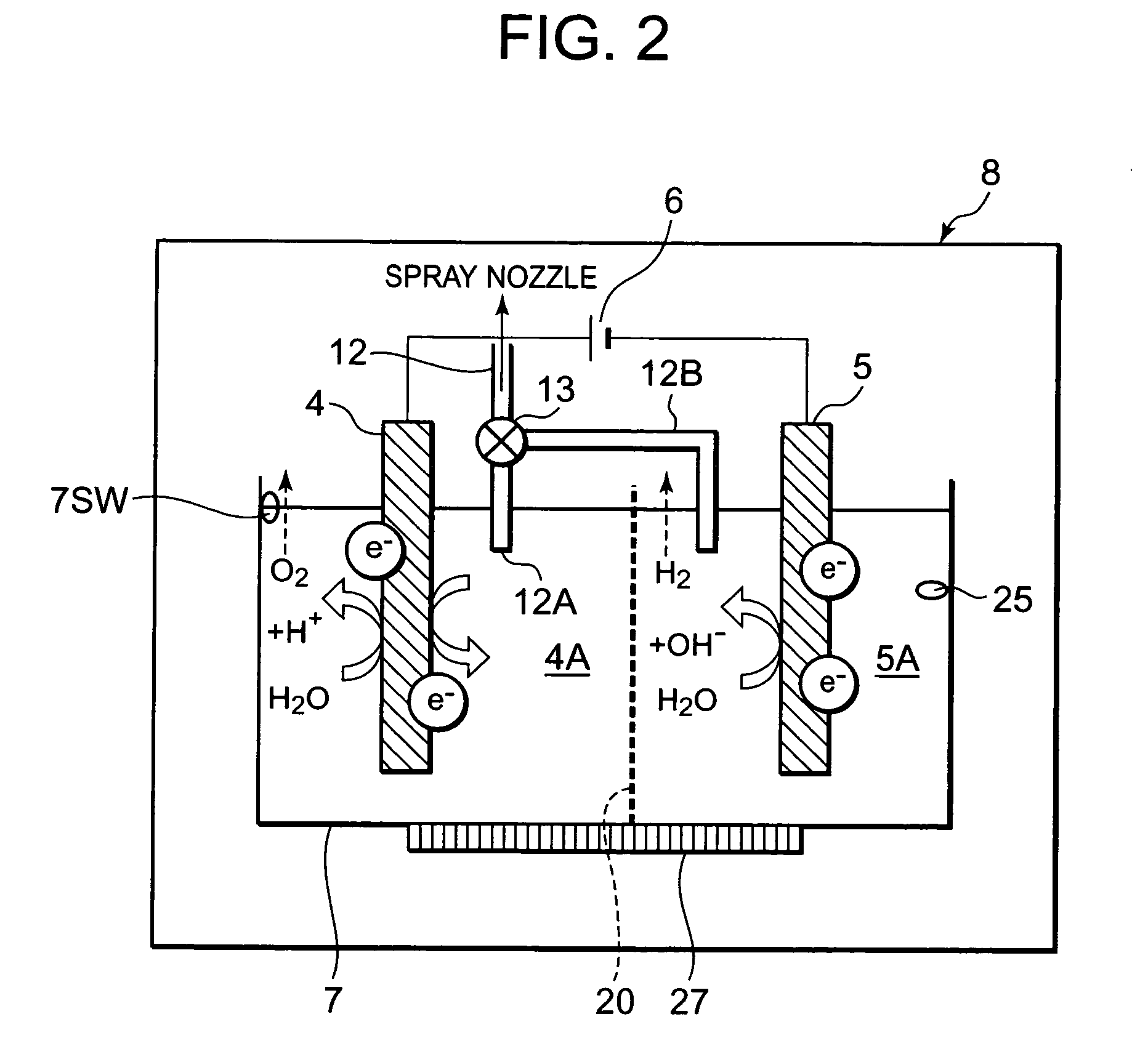
[0026]An object of the present invention is to effectively clean a heat exchanger without generating a hazardous substance such as NOx. An object to provide a cleaning device for the heat exchanger which can safely and effectively clean the heat exchanger is realized by electrolysis means for treating dew condensation water of the heat exchanger by an electrochemical technique, supply means for supplying electrolytic water produced by the treatment performed by this electrolysis means to an outer surface of the heat exchanger, and control means for controlling the electrolysis means and the supply means. An embodiment of the present invention will hereinafter be described in detail with reference to the drawings.

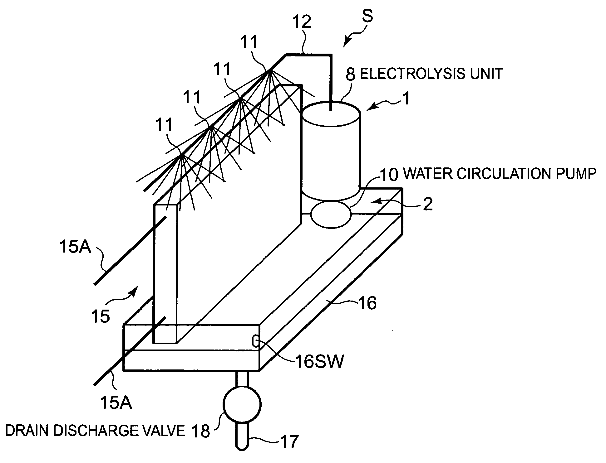
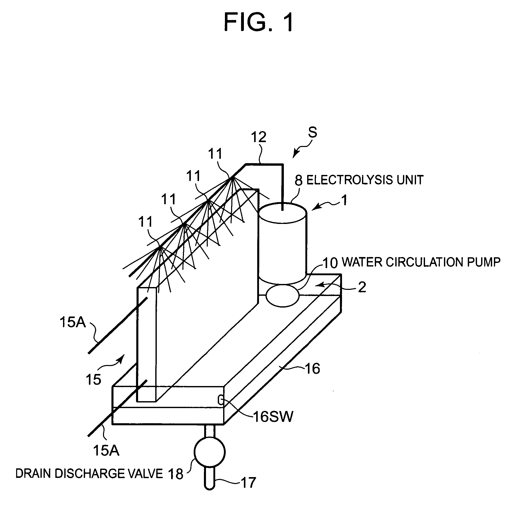
[0027]FIG. 1 is a schematic constitution diagram of a cleaning device S for a heat exchanger according to one embodiment of the present invention. The cleaning device S is a device for cleaning a heat exchanger 15 and removing germs from (cleaning) the heat exchanger. The cl...


PUM

PropertyMeasurementUnit
Temperatureaaaaaaaaaa

Abstract

There is disclosed a cleaning device for a heat exchanger which safely and effectively cleans the heat exchanger and which can sufficiently obtain a deodorizing effect and a sterilization effect. The cleaning device for the heat exchanger includes an electrolysis unit for treating dew condensation water of the heat exchanger by an electrochemical technique, a supply unit for supplying electrolytic water produced by the treatment performed by this electrolysis unit to an outer surface of the heat exchanger, and an control unit for controlling the electrolysis unit and the supply unit, and the control unit allows the electrolysis unit to electrolytically treat the dew condensation water of the heat exchanger and produce the electrolytic water, and allows the supply unit to supply the produced electrolytic water to the outer surface of the heat exchanger.

Description

BACKGROUND OF THE INVENTION[0001]The present invention relates to a cleaning device for a heat exchanger which removes mold, germs and the like attached to an outer surface of the heat exchanger.[0002]Heretofore, in a heat exchanger, for example, a heat exchanger which functions as an evaporator constituting a refrigerant cycle of an air conditioner, a refrigerant in the heat exchanger absorbs heat from surrounding air and consequently it evaporates, whereby a cooling function is exerted to cool a space to be cooled. In this case, when the refrigerant absorbs the heat from the surrounding air, water in the air condenses (dew-condenses) and attaches to the surface (the outer surface) of the heat exchanger in the form of water droplets. During operation, the water which attaches to the outer surface of the evaporator gradually grows and then drops down owing to a gravity, whereby the water is discharged therefrom. After the operation is stopped, however, the water remains on the outer...

Claims


Application Information

Patent Timeline
IPC IPC(8): C23F13/00F24F1/00F28F19/01
CPCB60H3/0092B60H1/32331C02F1/4672C02F2001/46185C02F2001/4619C02F2201/46115C02F2201/4612C02F2201/4618C02F2209/02F24F2221/22F28F2265/20F28G9/00F24F8/24
Inventor YAMAMOTO, TETSUYARAKUMA, TSUYOSHI
Owner SANYO ELECTRIC CO LTD
Why Eureka
Try Eureka