System and Process for Treatment and De-halogenation of Ballast Water

a ballast water and treatment system technology, applied in the field of systems, can solve the problems of potentially dangerous marine flora and fauna around the vessel, halogen-containing oxidizing agents, etc., and achieve the effect of preventing outbreaks

Active Publication Date: 2008-06-26
DE NORA WATER TECH
View PDF44 Cites 67 Cited by
  • Summary
  • Abstract
  • Description
  • Claims
  • Application Information

AI Technical Summary

Benefits of technology

[0006]The present invention provides a system and method for treating ballast water in a marine vessel. Ballast water is piped onto a vessel in one port or harbor and discharged upon reaching another port. On-site hypochlorite generation allows the ballast water to be treated on board the vessel before the ballast water is released in a distant port. Treating the ballast water with hypochlorite

Problems solved by technology
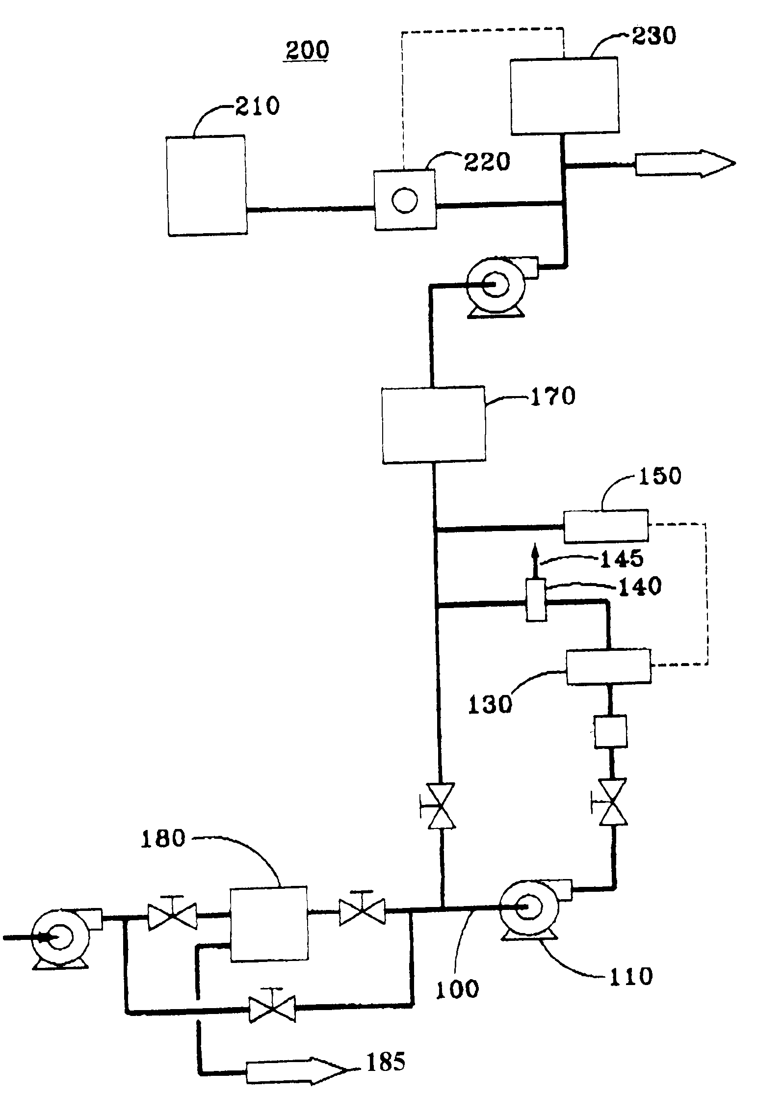
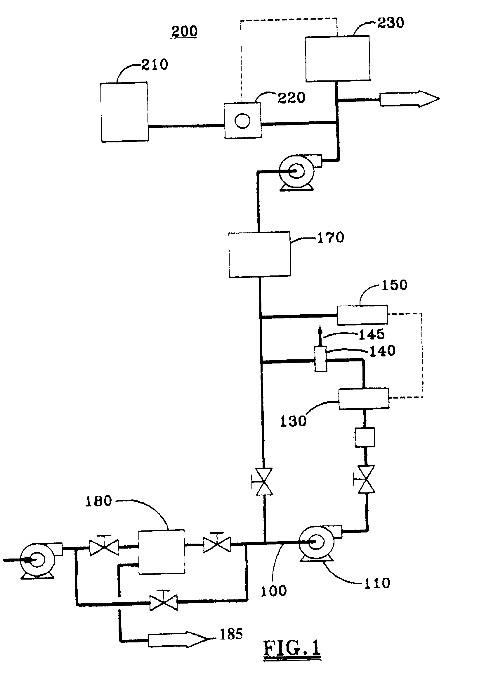
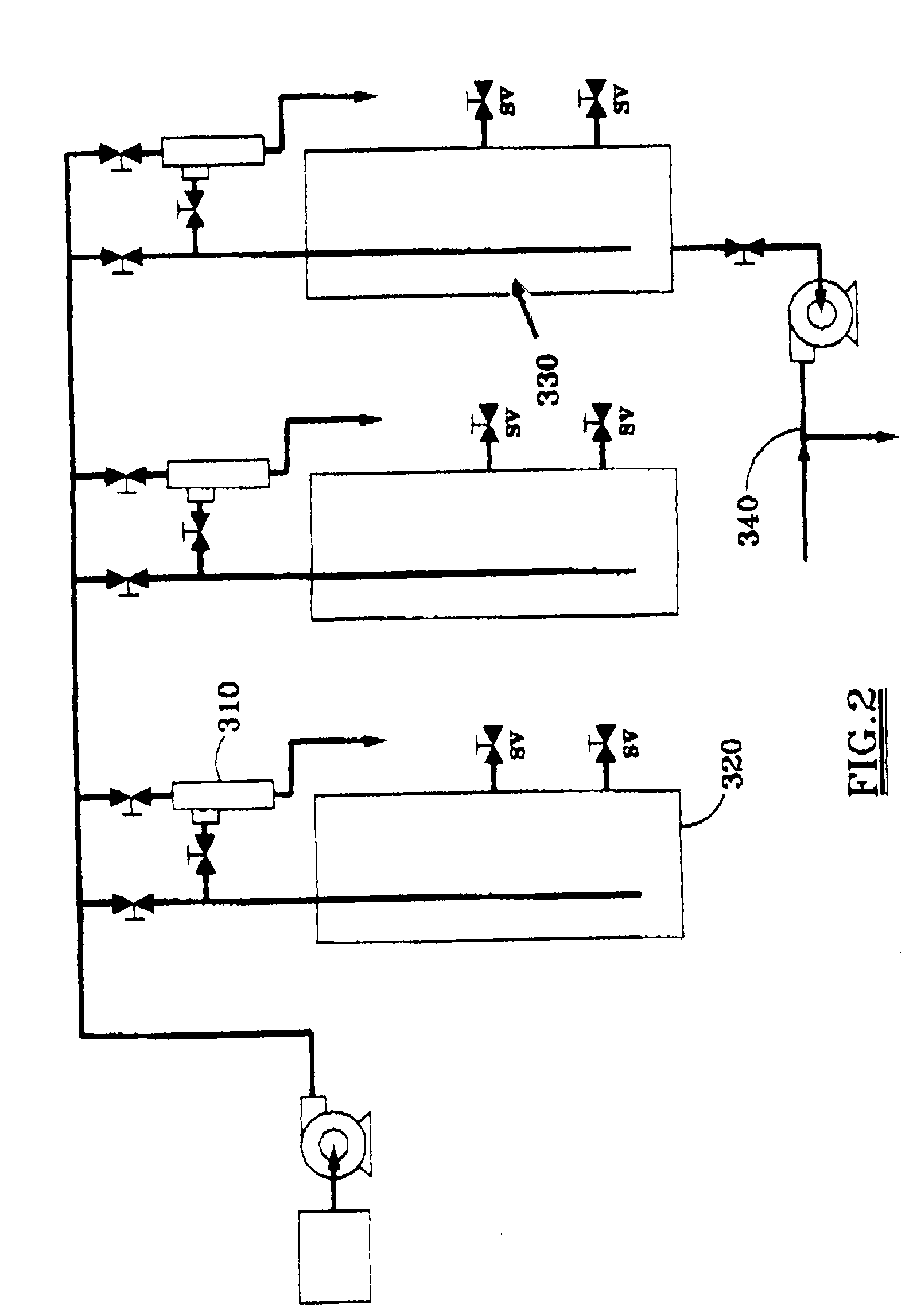
When the ballast water containing the halogens is released from the vessel the halogen-contain

Method used


Image

  • System and Process for Treatment and De-halogenation of Ballast Water
  • System and Process for Treatment and De-halogenation of Ballast Water
  • System and Process for Treatment and De-halogenation of Ballast Water

Examples


example 1

Results for Example 1

[0089]Total Residual Oxidant (TRO) levels declined steadily for the duration of the experiment. (FIG. 3). TRO in the nonfiltered test tanks dropped more than the filtered test tanks in the first 5 hours and then the TRO dissipated equally for the remaining time points.

[0090]Bacteria were greatly reduced in both treatments and showed minimal rebound over the 10 days of the experiment. There was a slight rebound of bacteria in the treatment without filtration.

[0091]Chlorophyll a is an indicator of phytoplankton. In the treated seawater, Chlorophyll a levels were at or below the detection limit starting with the 5-hour time point and continued to drop for both of the treatments.

[0092]In the control tanks, chlorophyll a levels declined over the duration of the experiment, likely due to the absence of light since all of the mesocosms were covered.

[0093]After the first treatment trial it was concluded that no statistical difference could be found between the two treat...

example 2

Sodium Hypochlorite Mesocosm October 2004

[0094]The second test of the sodium hypochlorite generator / filtration treatment system was started on Oct. 12, 2004. Two experiments were performed. The first experiment compared two treatments, filtration / chlorination (˜1.0 mg Cl2 / L) versus filtration only. The second experiment compared a chlorination dose of 1.0 mg Cl2 / L with a dose of 1.6 mg Cl2 / L. Each experiment included 4 mesocosms per treatment and 4 control tanks. The mesocosms were analyzed for Total Residual Oxidant (TRO) (mg Cl2 / L), culturable heterotrophic bacteria, chlorophyll a, and zooplankton at 5, 24, 48, and 240 hours following treatment. Culturable phytoplankton was enumerated in the first experiment. Samples were also collected at 5 hours for nutrient and total organic carbon (TOG) analysis. The temperature in the mesocosms fluctuated between 12.0° C. and 14.0° C.

Procedure

[0095]The procedure for Example 2 was the similar to the procedure used in Example 1 except for the p...


PUM

PropertyMeasurementUnit
Reduction potentialaaaaaaaaaa
Flow rateaaaaaaaaaa

Abstract

A system and process for de-halogenating ballast water before releasing the ballast water from the vessel. In one embodiment, the system comprises a means for measuring the halogen content of the ballast water, a reducing agent source in fluid communication with the ballast water, and a means for controlling the amount of reducing agent supplied to the ballast water. In one aspect, the means for measuring the halogen content comprises one or more oxidation/reduction potential analyzers. In another embodiment, the system comprises one or more hypochlorite electrolytic cells for generating hypochlorite to treat the ballast water.
One embodiment of the process for de-halogenating ballast water comprises measuring the oxidation/reduction potential of the ballast water and adding one or more reducing agents to the ballast water to de-halogenate the ballast water in response to the measured oxidation/reduction potential. In one aspect, the oxidation/reduction potential is modulated so that excess reducing agent is present in the ballast water.

Description

PRIORITY CLAIM[0001]This application is a Continuation-in-Part of U.S. application Ser. No. 11 / 037,642, filed Jan. 18, 2005FIELD OF THE INVENTION[0002]The system and process of this invention relate generally to a system and process for the treatment of ballast water to eliminate marine species and pathogenic bacteria from ballast water. More particularly, the system and process of this invention treats ballast water with hypochlorite produced on-site.BACKGROUND OF THE INVENTION[0003]Ballast water is used to balance the weight distribution in a marine vessel. Ballast water is pumped into tanks where it is stored to properly balance a vessel for a voyage. Often ballast water is taken on at one port and transported to another where it is emptied into the new port. This common practice has an inherent danger. Releasing the ballast water taken aboard from a distant location can be both harmful to the environment and dangerous to human and animals in a new port.[0004]The introduction of ...

Claims


Application Information

Patent Timeline
IPC IPC(8): B01D57/02B01D35/06
CPCB63J4/002B63J4/004G01N33/1846C02F2303/185C02F1/4674C02F1/70C02F9/00C02F2103/008C02F2201/46125C02F2209/005C02F2209/04C02F2209/20C02F2209/29C02F2209/40C02F2301/043C02F2303/04C02F1/76C02F2103/08
Inventor CHILDERS, HAROLD E.FERNANDEZ, RANDOLTOMATOUSEK, RUDOLF C.MOORE, JAMES B.HILL, DAVID W.
Owner DE NORA WATER TECH
Why Eureka
Try Eureka