

Method and apparatus for ammonia (NH3) generation
- Summary
- Abstract
- Description
- Claims
- Application Information
AI Technical Summary
Benefits of technology
Problems solved by technology
Method used
Image

Examples
Embodiment Construction
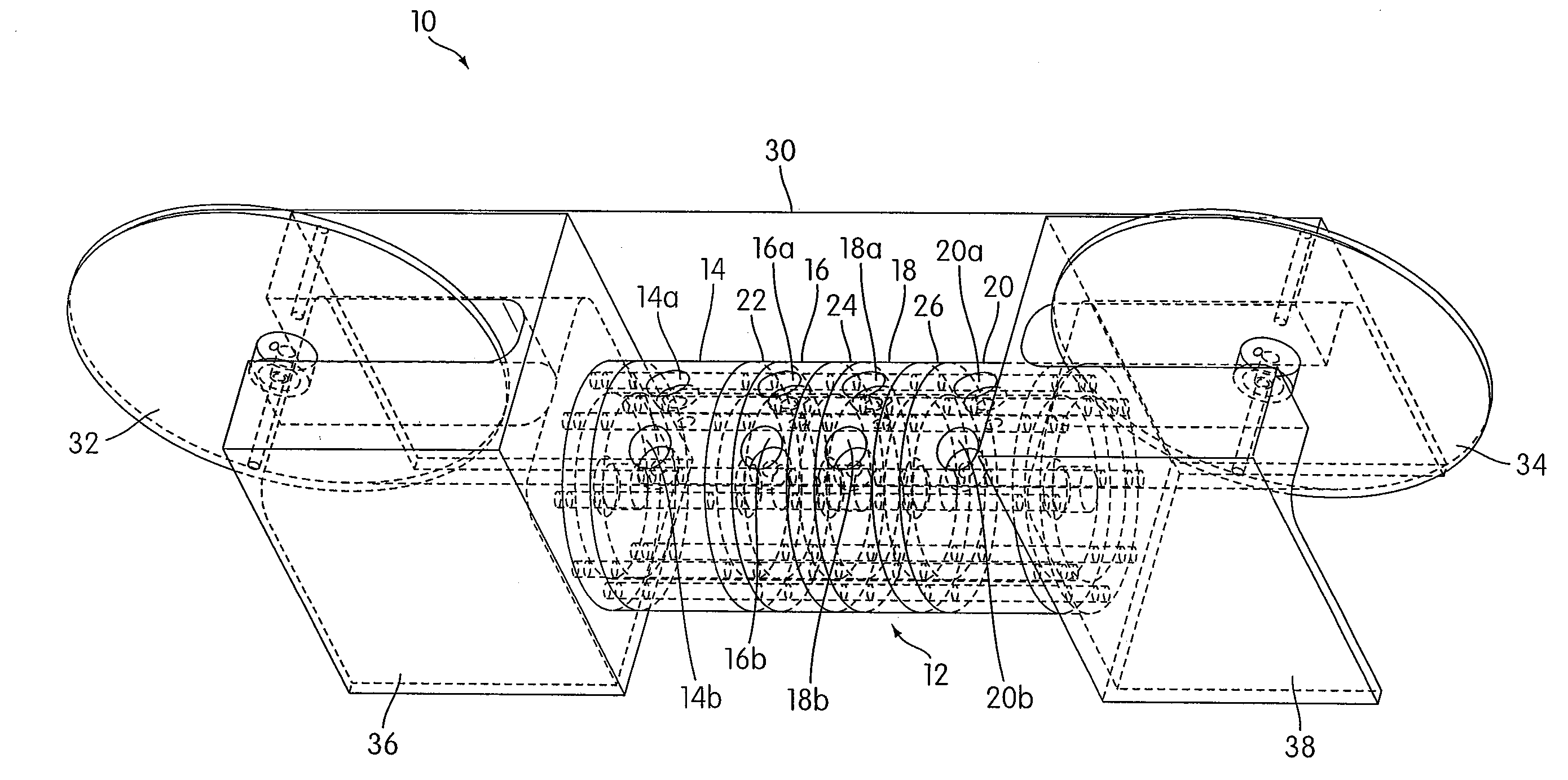
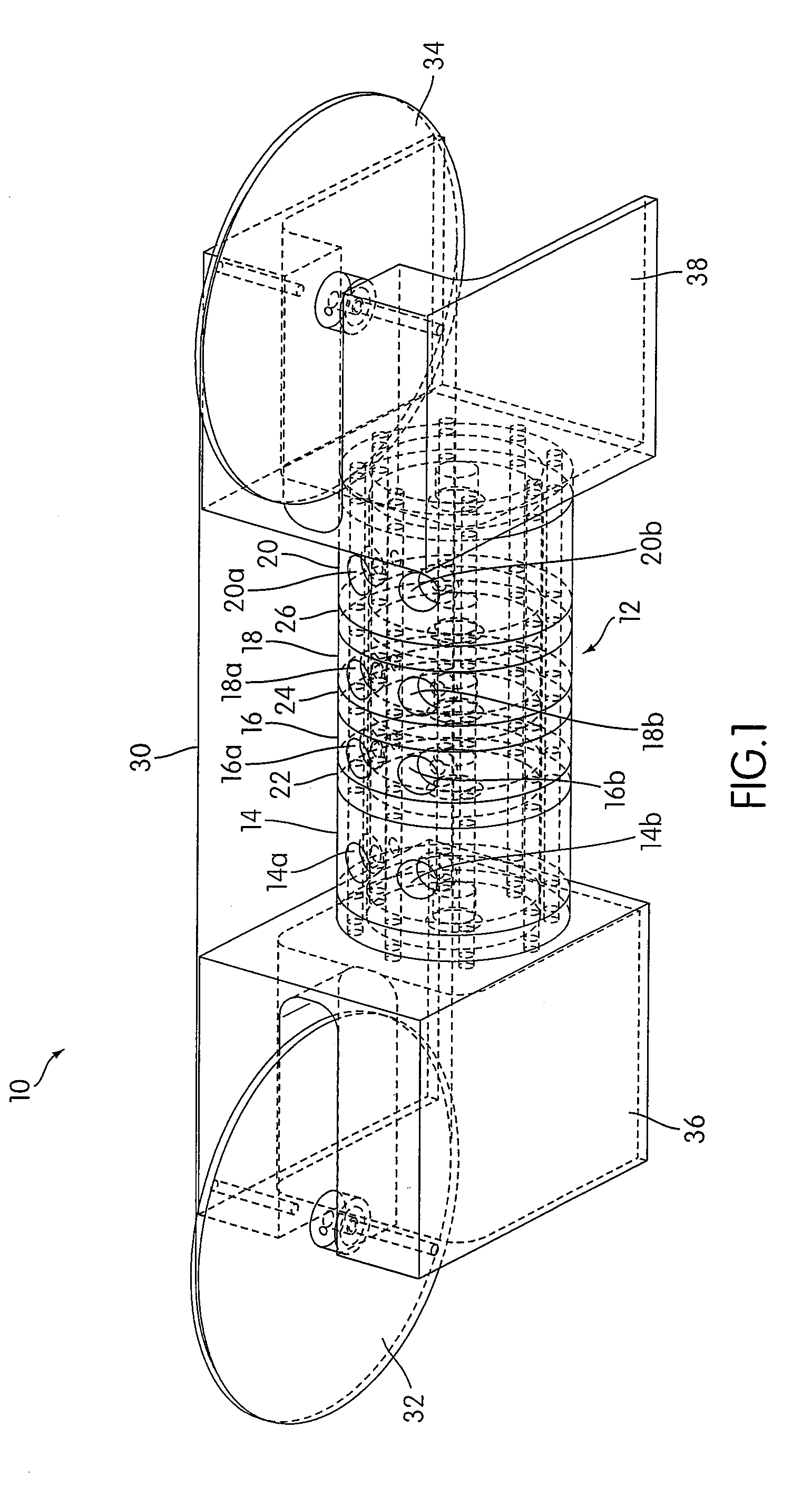
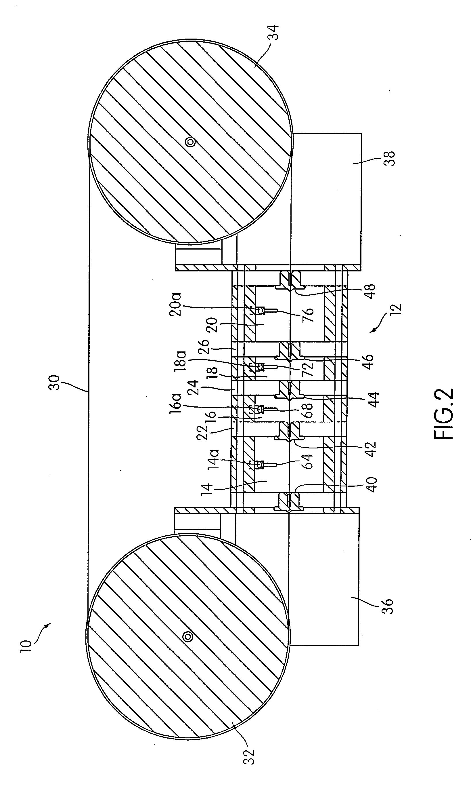
[0049]An apparatus 10 according to an embodiment of the present invention is illustrated in FIG. 1. As shown in FIG. 1, the apparatus 10 includes a housing 12 that includes a plurality of chambers, including a first chamber 14, a second chamber 16, a third chamber 18, and a fourth chamber 20. As illustrated, the first chamber 14 and the second chamber 16 may be separated by a first separator 22, the second chamber 16 and the third chamber 18 may be separated by a second separator 24, and the third chamber 18 and the fourth chamber 20 may be separated by a third separator 26. The separators 22, 24, and 26 are each connected to the housing 12 so as to form an air tight seal between each separator and the housing 12.
[0050]Although the housing 12 is illustrated as having a generally cylindrical shape, other shapes may be used in accordance with the present invention. For example, in some embodiments, the housing 12 may have a generally rectangular shape. The illustrated embodiment is no...
PUM
| Property | Measurement | Unit |
|---|---|---|
| Temperature | aaaaa | aaaaa |
| Pressure | aaaaa | aaaaa |
| Polarity | aaaaa | aaaaa |
Abstract
Description
Claims
Application Information