Apparatus for modifying surfaces of toner particles
a technology of toner particles and surfaces, applied in the field of toner particle surfaces modified by apparatus, can solve the problems of difficult control of surface properties of toner particles, insufficient achievement of the aim of making toner particles spherical, and quality stability problems of toner particles, so as to achieve high yield of toner particles, make toner particles highly spherical, and good toner
- Summary
- Abstract
- Description
- Claims
- Application Information
AI Technical Summary
Benefits of technology
Problems solved by technology
Method used
Image

Examples
example 1
[0209]
(by weight)Unsaturated polyester resin100 parts (unsaturated polyester resin composed ofpolyoxypropylene(2.2)-2,2-bis(4-hydroxyphenyl)propane,polyoxyethylene(2.2)-2,2-bis(4-hydroxyphenyl)propane,terephthalic acid, trimellitic anhydride and fumaricacid; weight-average molecular weight: 17,000; Tg:60° C.)Copper phthalocyanine pigment6 parts(C.I. Pigment Blue 15:3)Paraffin wax5 parts(maximum endothermic peak temperature: 73° C.)Charge control agent2 parts(aluminum complex of 3,5-di-tert-butylsalicylic acid)
[0210]The above materials were well mixed using Henschel mixer (FM-75 Model, manufactured by Mitsui Miike Engineering Corporation). Thereafter, the mixture obtained was kneaded by means of a twin-screw kneader (PCM-30 Model, manufactured by Ikegai Corp.) set to a temperature of 110° C. The kneaded product obtained was cooled, and then crushed (coarsely pulverized) by means of a hammer mill to a size of 1 mm or less to obtain a coarsely pulverized product for producing toner par...
example 2
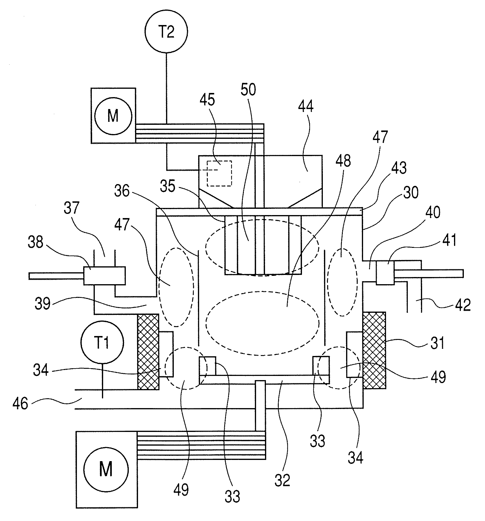
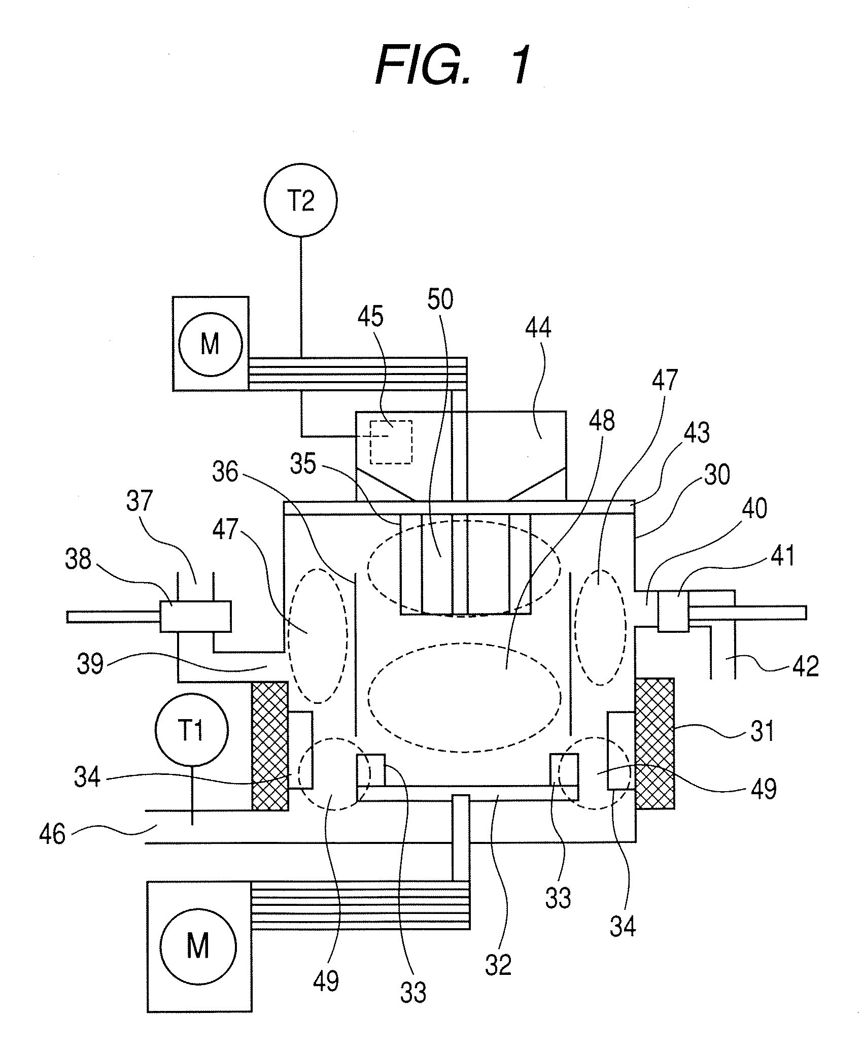
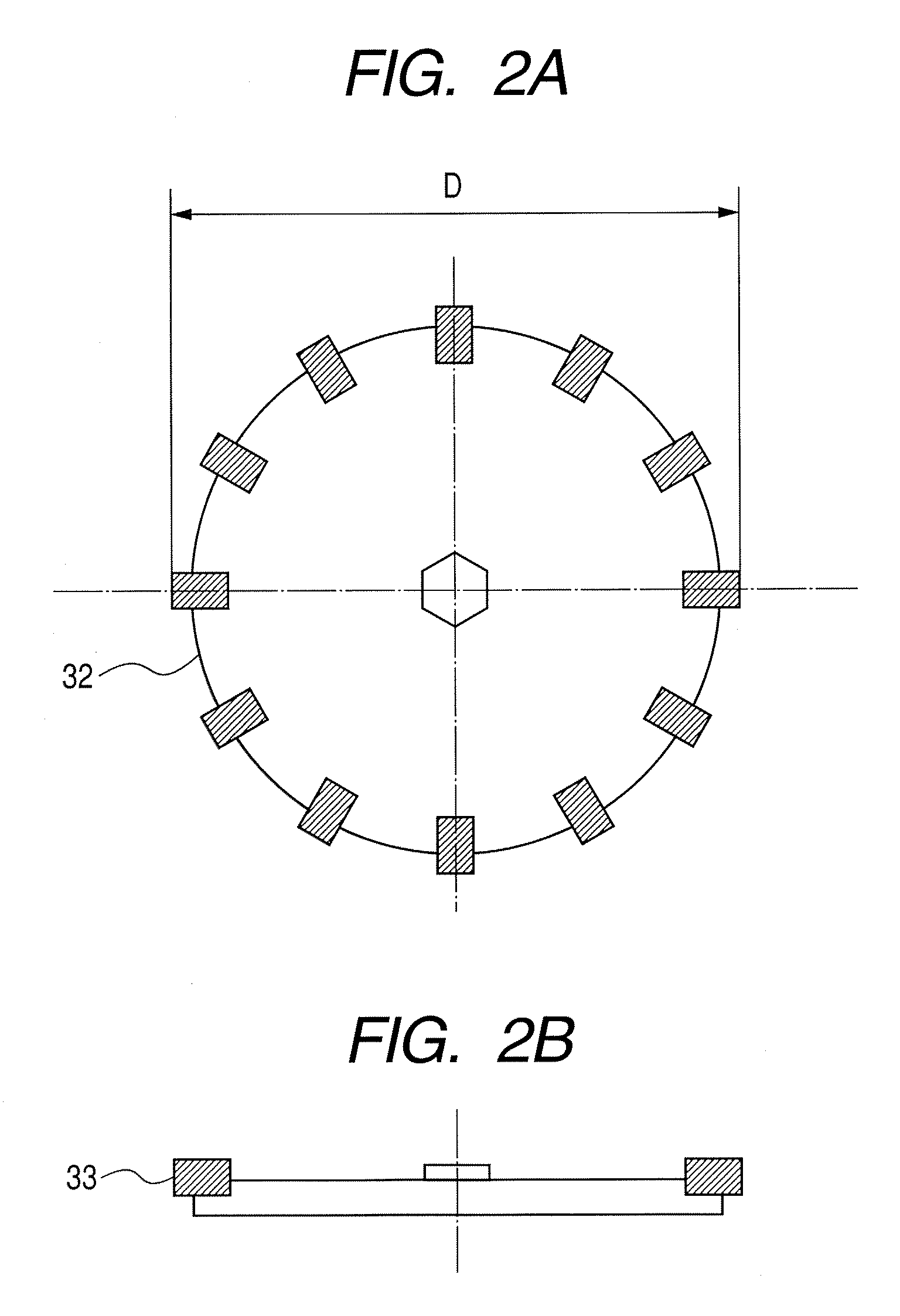
[0226]The toner material powder particles obtained in Example 1 were surface-modified using the batch-wise surface modifying apparatus shown in FIG. 1. In making the surface modification, the amount of the toner material powder particles introduced, the rotational peripheral speed of the classifying rotor 35, the rotational peripheral speed of the dispersing rotor 32 and the surface modification time were set equal to those in Example 1, and the minimum gap between the rectangular disks 33 provided at the top surface of the dispersing rotor 32 and the liner 34 was set to 3.0 mm. Also, the height H of the rectangular disks 33 provided at the top surface of the dispersing rotor 32 of the batch-wise surface modifying apparatus shown in FIG. 1 was set to 24.0 (mm) and the external diameter D of the dispersing rotor 32 was set to 400 (mm). Therefore, the value of α calculated from H=√{square root over (D)}×α+10.5 was 0.68. Also, the number of the rectangular disks 33 provided at the top ...
example 3
[0229]The toner material powder particles obtained in Example 1 were surface-modified using the batch-wise surface modifying apparatus shown in FIG. 1. In making the surface modification, the amount of the toner material powder particles introduced, the rotational peripheral speed of the classifying rotor 35, the rotational peripheral speed of the dispersing rotor 32 and the surface modification time were set equal to those in Example 1, and the minimum gap between the rectangular disks 33 provided at the top surface of the dispersing rotor 32 and the liner 34 was set to 1.0 mm. Also, the height H of the rectangular disks 33 provided at the top surface of the dispersing rotor 32 of the batch-wise surface modifying apparatus shown in FIG. 1 was set to 24.0 (mm) and the external diameter D of the dispersing rotor 32 was set to 400 (mm). Therefore, the value of α calculated from H=√{square root over (D)}×α+10.5 was 0.68. Also, the number of the rectangular disks 33 provided at the top ...
PUM
| Property | Measurement | Unit |
|---|---|---|
| outer diameter D | aaaaa | aaaaa |
| particle diameter | aaaaa | aaaaa |
| weight-average particle diameter | aaaaa | aaaaa |
Abstract
Description
Claims
Application Information
 - Generate Ideas
- Intellectual Property
- Life Sciences
- Materials
- Tech Scout
- Unparalleled Data Quality
- Higher Quality Content
- 60% Fewer Hallucinations
Browse by: Latest US Patents, China's latest patents, Technical Efficacy Thesaurus, Application Domain, Technology Topic, Popular Technical Reports.
© 2025 PatSnap. All rights reserved.Legal|Privacy policy|Modern Slavery Act Transparency Statement|Sitemap|About US| Contact US: help@patsnap.com