Laser microscope and control method for the same

Active Publication Date: 2008-06-26
EVIDENT CORP
View PDF9 Cites 15 Cited by
  • Summary
  • Abstract
  • Description
  • Claims
  • Application Information

AI Technical Summary

Benefits of technology

[0013]The present invention provides a laser microscope that can achieve a required field number and numerical aperture for microscope observation at a sca

Problems solved by technology

Although the laser microscope using a galvanometer mirror can ensure a sufficient deflection angle of laser light, there is a problem in that the required video-rate cannot be realized because its scanning speed is slow.
When the beam diameter of the laser light to be made incident on the acousto-optic device is large, the delay effect of an acoustic wav

Method used


Image

  • Laser microscope and control method for the same
  • Laser microscope and control method for the same
  • Laser microscope and control method for the same

Examples


Embodiment Construction

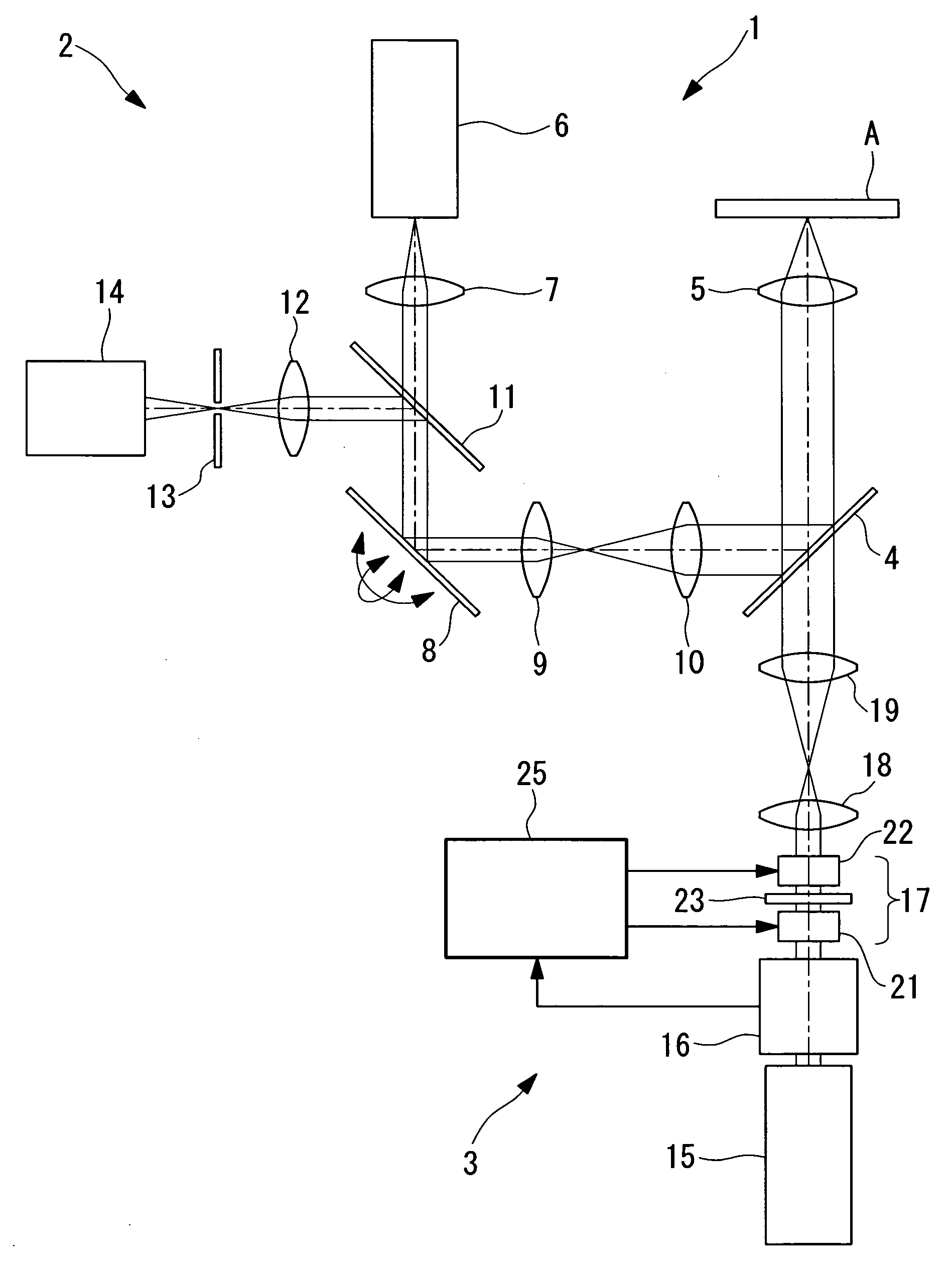
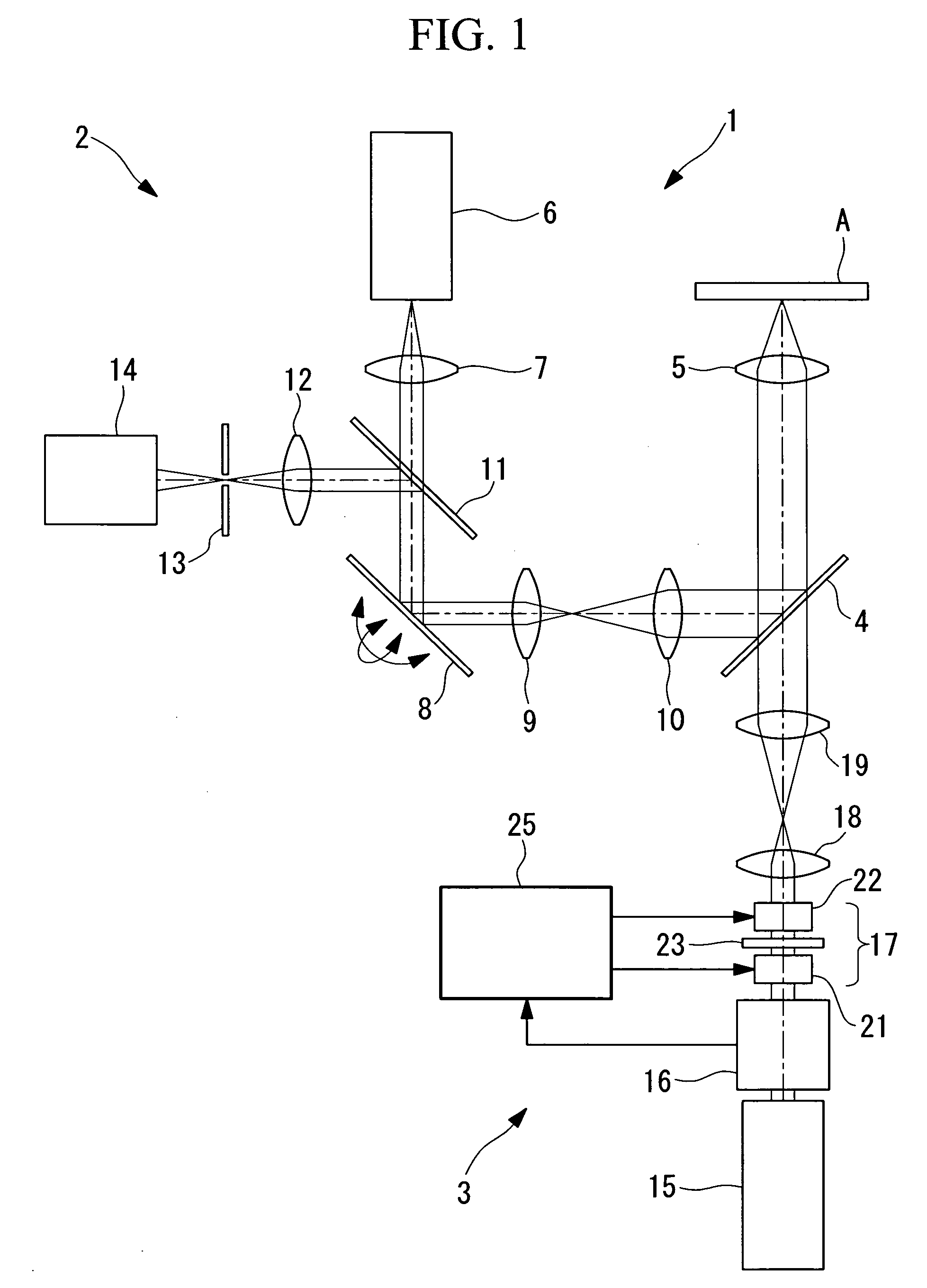
[0075]A laser microscope 1 and a control method thereof according to an embodiment of the present invention will be described below with reference to FIGS. 1 and 2.

[0076]As shown in FIG. 1, the laser microscope 1 according to this embodiment includes an observation optical system 2, a light-stimulus optical system 3, a dichroic mirror 4 for combining optical axes of these optical systems 2 and 3, and an objective lens 5 for irradiating a specimen A with laser light and collecting fluorescence emitted from the specimen A due to irradiation with the laser light.

[0077]The observation optical system 2 includes an observation laser light source 6 for emitting the laser light, a collimator lens 7 for converting the laser light from the laser light source 6 to substantially collimated light, a scanning unit 8 for two-dimensionally scanning the laser light substantially collimated by the collimator lens 7, a pupil-projection lens 9 for focusing the laser light scanned by the scanning unit 8...


PUM


Abstract

It is possible to achieve a required field number and numerical aperture for microscope observation at a scanning speed equal to video-rate or higher and also to change the scanning speed with a simple configuration. The invention provides a laser microscope including a laser light source; a scanning unit configured to scan a specimen with laser light emitted from the laser light source; and an objective lens configured to focus the laser light scanned by the scanning unit on the specimen. The scanning unit is provided with an electro-optical deflecting element including an electro-optical crystal in which a refractive index gradient is induced by injecting electric current.

Description

BACKGROUND OF THE INVENTION[0001]1. Field of the Invention[0002]The present invention relates to laser microscopes and to a method for controlling the same.[0003]This application is based on Japanese Patent Application No. 2006-347892, the content of which is incorporated herein by reference.[0004]2. Description of Related Art[0005]A known laser microscope using a point scanning method employs a galvanometer mirror, an acousto-optic device, or an electro-optical element as a scanning unit.[0006]Although the laser microscope using a galvanometer mirror can ensure a sufficient deflection angle of laser light, there is a problem in that the required video-rate cannot be realized because its scanning speed is slow.[0007]There are known light scanning devices capable of scanning laser light at the required video rate using an acousto-optic device (for example, see Japanese Unexamined Patent Application, Publication No. HEI-8-327936), and using an electro-optical element (for example, see...

Claims


Application Information

Patent Timeline
IPC IPC(8): G02B21/00
CPCG02B21/0036
Inventor ARAYA, AKINORINAKATA, TATSUOUENO, MAKIO
Owner EVIDENT CORP
Why Eureka
Try Eureka