Oil supply method of two-stage screw compressor, two-stage screw compressor applying the method, and method of operating refrigerating machine having the compressor

a compressor and screw technology, applied in the direction of machines/engines, rotary/oscillating piston pump components, liquid fuel engines, etc., can solve the problems of reducing volumetric efficiency, scuffing of rotors, and increasing gas charge toward the suction side, so as to reduce the volumetric efficiency of the low-pressure stage compressor. , the effect of reducing the volumetric efficiency

Inactive Publication Date: 2008-06-26
MAYEKAWA MFG CO LTD
View PDF13 Cites 19 Cited by
  • Summary
  • Abstract
  • Description
  • Claims
  • Application Information

AI Technical Summary

Benefits of technology

[0052]According to the oil supply method of the invention, lubricating oil supplied to the bearing parts of the compressor is introduced to the compression cavities of the high-pressure stage compressor after lubricating the bearing parts, influence of operating gas released by flash evaporation from the lubricating oil injected into the compression cavities is limited only to the high-pressure stage compressor and amounts of the released gas is reduced, so volumetric efficiency is considerably increased as compared with the conventional oil supply method, and compression efficiency can be increased.
[0053]By controlling lubricating oil supply pressure to the bearing parts of the compressor to suffice the formula presented above, oil injection into the compression cavities of the high-pressure stage compressor can be performed without inducing occurrence of blow back of operating gas from the compression cavities toward the bearing parts.
[0054]According to the two-stage screw compressor of the invention, an oil conduit line for supplying the lubricating oil to the bearing parts in the two-stage compressor, a throttle valve provided to said oil conduit line, and an oil passage which brings the bearing parts in communication with a series of compression cavities produced by a pair of meshing rotors of the high-pressure stage compressor as the rotors rotate, are provided, and preferably an oil pump is provided to the oil conduit line, and lubricating oil supplied to the bearing parts is injected into the compression cavities of the high-pressure stage compressor after lubricating the bearing parts, so influence of operating gas released by flash evaporation from the lubricating oil injected into the compression cavities is limited only to the high-pressure stage compressor and amounts of the released gas is reduced and volumetric efficiency is considerably increased as compared with the conventional oil supply method, as

Problems solved by technology

Such a screw compressor requires a large amount of lubricating oil for lubricating the bearings and shaft seal element and for lubricating the rotors and cooling the gas charge.
When operating gas dissolving type refrigerating machine oil is used as lubricating oil, operating gas dissolved in the oil is flash-evaporated from the oil in the compression cavities, which induces early pressure rise in the compression cavities resulting in increased leak of the gas charge toward the suction side and decreased volumetric efficiency.
However, when discharge temperature is raised too much, scuffing of rotors occurs due to thermal expansion of the rotors lubrication of the bearings and shaft seal elements becomes insufficient due to

Method used


Image

  • Oil supply method of two-stage screw compressor, two-stage screw compressor applying the method, and method of operating refrigerating machine having the compressor
  • Oil supply method of two-stage screw compressor, two-stage screw compressor applying the method, and method of operating refrigerating machine having the compressor
  • Oil supply method of two-stage screw compressor, two-stage screw compressor applying the method, and method of operating refrigerating machine having the compressor

Examples


first embodiment

THE FIRST EMBODIMENT

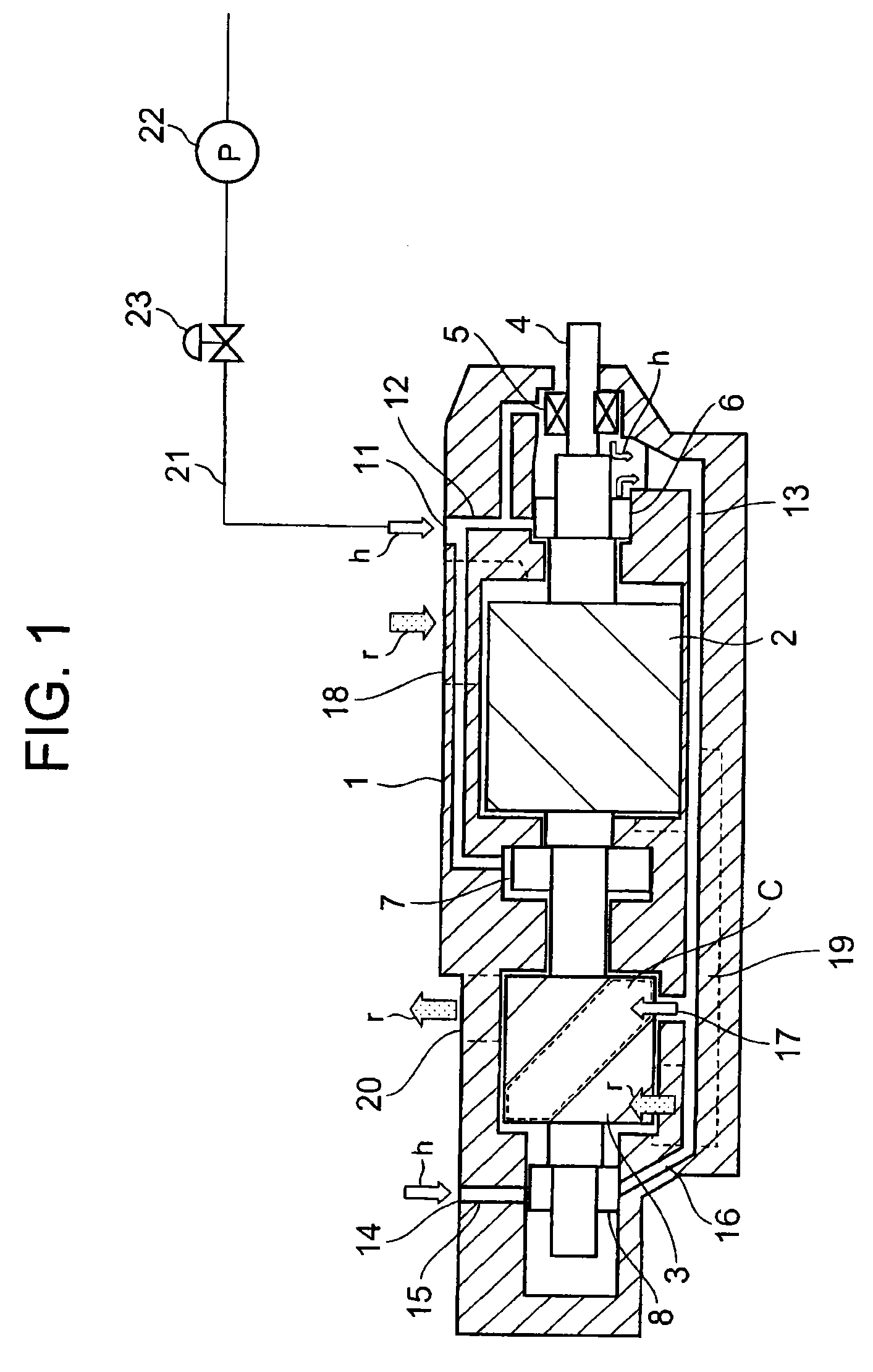
[0091]Referring to FIG. 1 showing a first embodiment of the invention, reference numeral 1 is a casing housing male and female rotors of a low-pressure stage compressor 2 and male and female rotors of a high-pressure stage compressor 3. Reference numeral 4 is a common rotor shaft connecting the male rotors of the lower and higher pressure compressors 2 and 3. The rotor shaft 4 is connected to an electric motor not shown in the drawing at the suction side of the low-pressure stage compressor. Reference numeral 5 is a shaft seal element (mechanical seal), 6˜8 are bearings supporting the rotor shaft 4 for rotation at the suction side of the low-pressure stage compressor, at the intermediate part between the lower and higher pressure compressors, and at the suction side of the high-pressure stage compressor. A common female rotor shaft not shown in the drawing is supported by bearings in the same way.

[0092]Reference numeral 11 is an oil supply port for supplying lubr...

second embodiment

THE SECOND EMBODIMENT

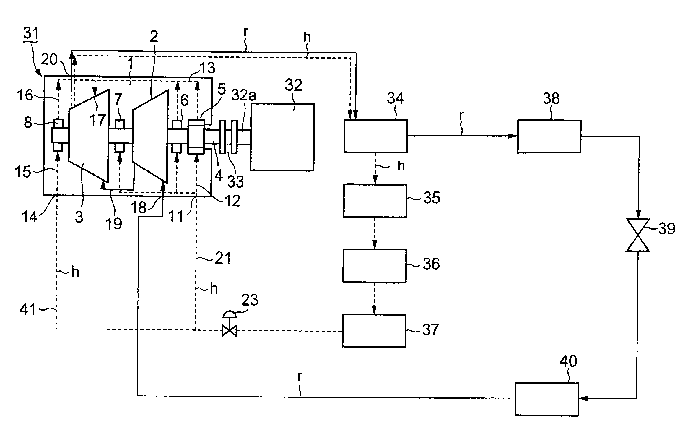
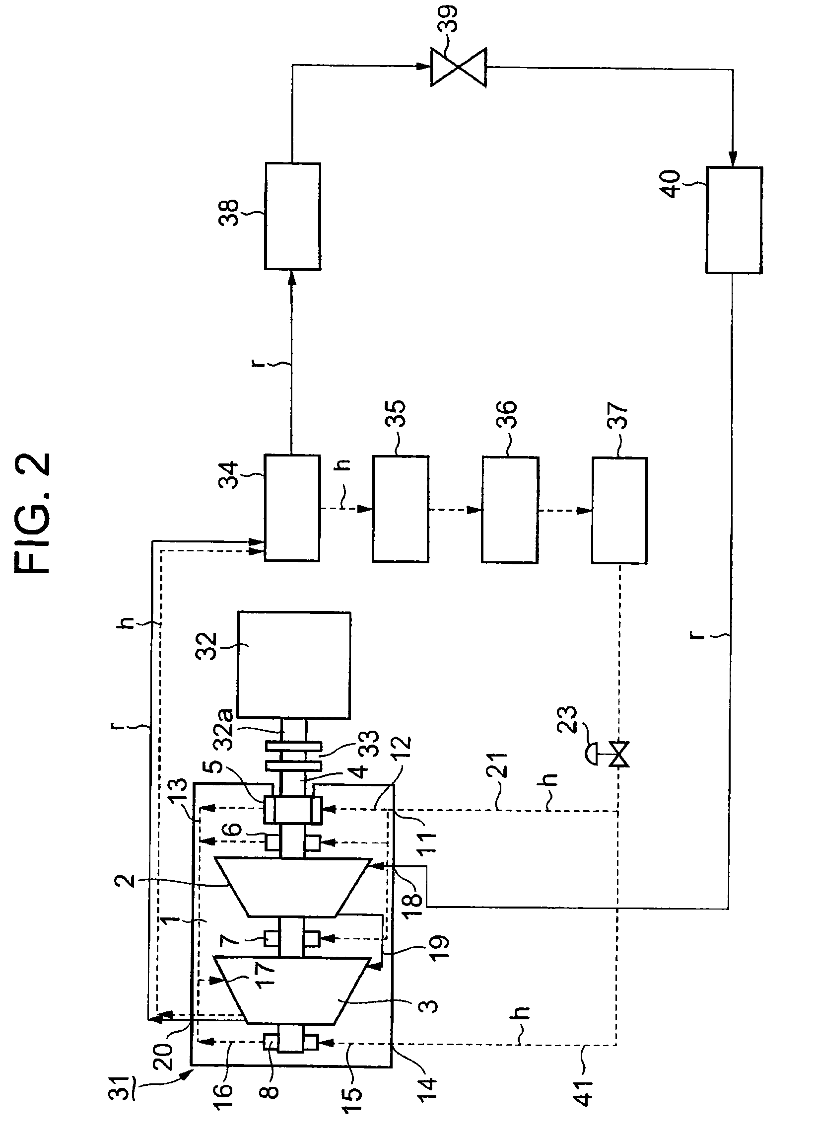
[0112]Next, a second embodiment of the invention will be explained referring to FIGS. 2 and 3. In the drawings, reference numeral 31 is a two-stage screw compressor. The compressor is composed the same as the screw compressor of FIG. 1, and constituents the same as those of the compressor of FIG. 1 is denoted by the same reference numerals, and explanation is omitted.

[0113]Reference numeral 32 is an electric motor for driving the common rotor shaft 4 of the lower pressure and high-pressure stage compressor 2 and 3. A drive shaft 32a of the motor 32 is connected to the common rotor shaft 4 by means of a coupling 33. Reference symbol r indicates a refrigerant gas, and h indicates lubricating oil in which refrigerant gas is dissolved. The refrigerant gas r and lubricating oil h is discharged from the discharge port 20 of the high pressure stage compressor 3 together, the lubricating oil h is separated from the refrigerant gas r in an oil separator 34. Then the refr...


PUM


Abstract

A method of supplying lubrication oil to a two-stage screw compressor is disclosed in which a low-pressure stage screw compressor and a high-pressure stage screw compressor are integrally constructed. A compression space is formed by a male rotor and a female rotor, and operation gas is fed for compression to the compression space. The method prevents degradation of volumetric efficiency caused by return of lubrication oil, coming from a bearing and a shaft sealing device, to the low-pressure stage screw compressor, and as a result, refrigeration capacity is improved and the amount of the lubrication oil is reduced.

Description

[0001]This is a continuation of International Application PCT / JP2005 / 011911 (published as WO 2007 / 000815) having an international filing date of 29 Jun. 2005, the disclosure of which, in its entirety, including the drawings, claims and the specification thereof, is incorporated herein by reference.TECHNICAL FIELD[0002]The present invention is related to a method of supplying refrigerating machine oil dissolving operating gas to a two-stage screw compressor in order to prevent exacerbation in volumetric efficiency of the compressor due to operating gas flash evaporated from the refrigerating machine oil, a two-stage screw compressor to which the method is applied, and a refrigerating machine using the two-stage screw compressor as its constituent compressor.BACKGROUND ART[0003]Generally, in a screw compressor, lubricating oil is supplied to bearings supporting rotors and oil is injected into the compression cavities formed by the rotors and rotor casing to aid sealing the gap between...

Claims


Application Information

Patent Timeline
IPC IPC(8): F04C15/00F01M1/00
CPCF04C18/16F04C29/02F04C23/001
Inventor KISHI, TAKAYUKIYAMADA, KAZUYASAKAGUCHI, TOSHIYUKITAKENOSHITA, TOMOO
Owner MAYEKAWA MFG CO LTD
Why Eureka
Try Eureka