Microorganism testing device

a microorganism and testing device technology, applied in the field of microorganism testing devices, can solve the problems of unfavorable measurement, small impurities, complex operations, etc., and achieve the effects of reducing the work load of the tester, reducing the possibility of the tester being exposed to a dyeing reagent, and reducing the cost of reagents

Inactive Publication Date: 2008-06-26
HITACHI ENG & SERVICES CO LTD
View PDF3 Cites 24 Cited by
  • Summary
  • Abstract
  • Description
  • Claims
  • Application Information

AI Technical Summary

Benefits of technology

[0015]Accordingly, work load of a tester, and a possibility that a tester is exposed to a dyeing reagent are reduced. Thereby, stable measurement results may be obtained, not depending on the skill of a tester. Moreover, required reagent costs may be reduced, because a surplus amount of used dyeing reagents may be decreased.

Problems solved by technology

Furthermore, small impurities also have a possibility to exert an unfavorable influence upon measurement results, for example, because the impurities produce auto-fluorescence.
These operations are complex in the same manner as the dyeing operations to require a professional skill.

Method used


Image

  • Microorganism testing device
  • Microorganism testing device
  • Microorganism testing device

Examples


example 1

[0055]A measurement chip 10 is used for measuring bacteria in liquid, such as drinking water and juice, including very few residual foods wherein the measuring is performed, using one kind of a dyeing reagent.

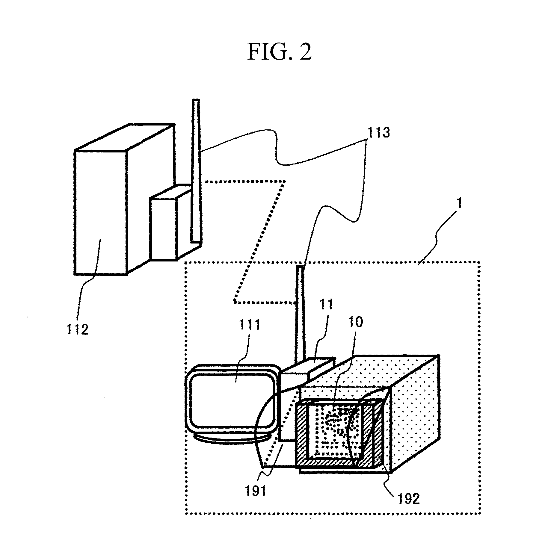
[0056]FIG. 2 is a schematic view of the microorganism testing device 1. The microorganism testing device 1 is used in a state in which the measurement chip 10 is set in a holder 192. The measurement chip 10 is fixed to the side of the microorganism testing device 1, using the holder 192 and a lid 191. An optimal process for measurement of the number of bacteria may be executed according to various kinds of specimens by changing the kind of the set measurement chip 10. A system device 11 performs control of the microorganism testing device 1, and processing of electric signals output from the microorganism testing device 1, and an output device 111 outputs obtained inspection results.

[0057]Moreover, the system device 11 exchanges data with a server 112 through a communication de...

example 2

[0089]There will be described an example using a measurement chip 100 in which viable bacteria and killed bacteria in liquid including a few residual foods such as drinking water and juice, are measured using two kinds of dyeing reagents.

[0090]The number of viable bacteria in a specimen may be measured by dyeing the cells in different colors with different dyeing pigments. Dyeing killed bacteria and viable bacteria in different colors is performed in such a way that killed bacteria dyeing pigment which dyes a killed bacterium are added to a specimen, and viable-and-killed bacteria dyeing pigment which dyes killed-and-viable bacteria are added after a predetermined time.

[0091]FIG. 15 is a plan view of a measurement chip 20. The measurement chip 20 has a structure in which another reaction container is added to the measurement chip 10 (FIG. 5). Among two reaction containers, a reaction container for holding killed bacteria dyeing pigment 1531 is assumed to be a killed bacteria dyeing ...

example 3

[0101]An example using the measurement chip 30 for measurement of viable bacteria and killed bacteria in such a specimen including residual foods as suspensions of foods will be described.

[0102]Influence of residual foods on measurement results is made to the minimum by adding a process of removing the residual foods included in the specimen before mixing the specimen and the dyeing pigment. The specimen used here is obtained by stomaching of foods to be inspected after adding physiological salt solution with a mass ratio of ten to the foods.

[0103]FIG. 16 is a plan view of the measurement chip 30. In the measurement chip 30, a residual food removing portion 16 is added to the measurement chip 20 (FIG. 15). The specimen container 1511, the residual food removing portion 16, the killed bacteria reagent holding container 153, the viable-and-killed bacteria dyeing reagent holding container 154, the specimen detection portion 18, and the detection liquid waste container 163 are connected...


PUM

PropertyMeasurementUnit
diameteraaaaaaaaaa
widthaaaaaaaaaa
widthaaaaaaaaaa

Abstract

Pretreatment of residual food removal and bacteria dyeing, and measurement of the number of bacteria using the fluorescence flow cytometry method, are stably performed by easy operations.
A measurement chip 10 includes: a specimen container 151; a reaction container 170 for mixing a specimen and a dyeing reagent into a liquid mixture; a bacteria detection portion 18 being irradiated with excitation light; a detection liquid waste container 163 into which liquid mixture which has passed the bacteria detection portion enters; a solution flow path 157 which connects the specimen container, the reaction container and the bacteria detection portion, and ventilation ports 1631 through 1633 which are connected to the specimen container, the reaction container and the detection liquid waste container, through a air flow path and is connected to a chip connecting tube. Bacteria are detected in the bacteria detection portion 18 by switching of the states of the specimen container, the reaction container, and the detection liquid waste container between a sealed state and a state open to the atmospheric pressure, by moving the specimen to the reaction container 170 to mix and stir the specimen and the dyeing reagent, and by moving of the liquid mixture to the detection liquid waste container 163.

Description

BACKGROUND OF THE INVENTION[0001]1. Field of the Invention[0002]The present invention relates to a microorganism testing device measuring microorganisms included in foods.[0003]2. Description of the Related Art[0004]Conventionally, there have been known measuring devices which execute various kinds of methods for quick and simple measurement of the number of viable bacteria. Especially, a device for measuring the number of bacteria has become of major interest as a technique for quick and direct measurement of the number of viable bacteria, wherein the device uses a fluorescence flow cytometry method.[0005]The fluorescence flow cytometry method is a particle measuring method, in which the diameter of specimen flow including specimens dyed with a fluorochrome is made smaller, and the specimen is discharged in a flow one by one for measurement. A device for measuring the number of bacteria, which uses the above method, may measure a specimen one by one in a short time.[0006]Moreover, ...

Claims


Application Information

Patent Timeline
Patent Type & Authority Applications(United States)
IPC IPC(8): C12M1/00
CPCG01N15/1484G01N2015/1486G01N21/6428
Inventor TAKENAKA, KEISASAKI, YASUHIKOMIYAKE, RYO
Owner HITACHI ENG & SERVICES CO LTD
Why Eureka
Try Eureka