
Virtual interface and system for controlling a device

a virtual interface and device technology, applied in the field of virtual interfaces and systems for controlling devices, can solve the problems of wasting processing resources, sacrificing the quality of content items, and difficult seamless integration, and achieve the effect of freeing up the resources of the main server

Inactive Publication Date: 2008-06-26
STROSS MARK
View PDF21 Cites 80 Cited by
  • Summary
  • Abstract
  • Description
  • Claims
  • Application Information

AI Technical Summary

Benefits of technology

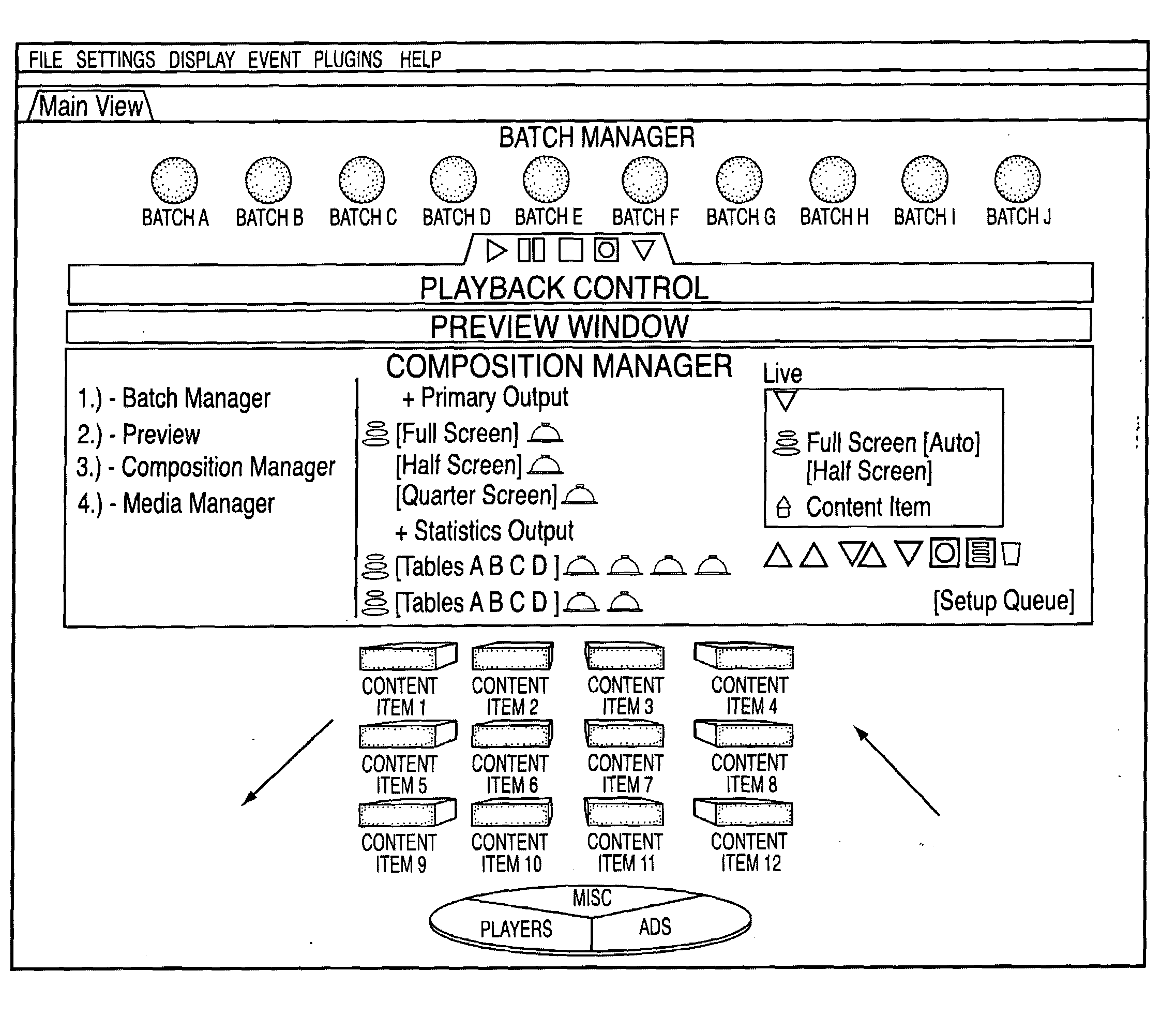
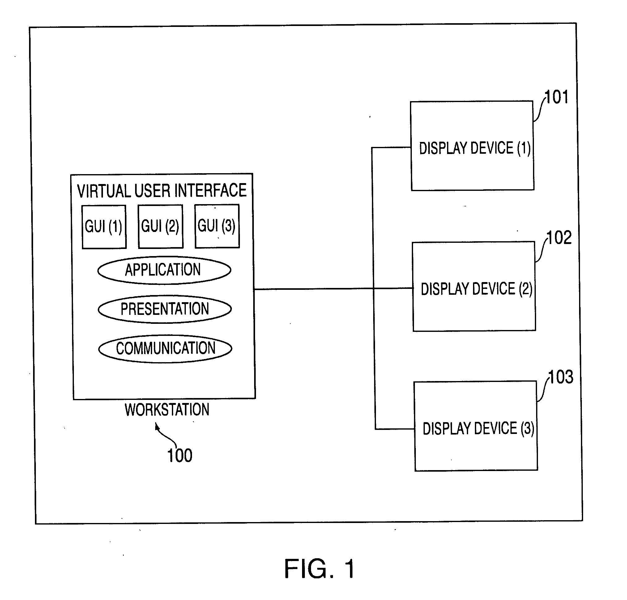
[0012]The present invention provides a novel system and method of operating a number of real-world devices. In its preferred form, the invention provides a three-dimensional VUI for operation and previewing of multiple displays. First, a radical change in the hardware architecture allocates graphics processing operations to a graphics processing unit (GPU) and other networked hardware. Offloading the rendering of content and the video output path to Sub-Servers frees up the resources of a Main Server.
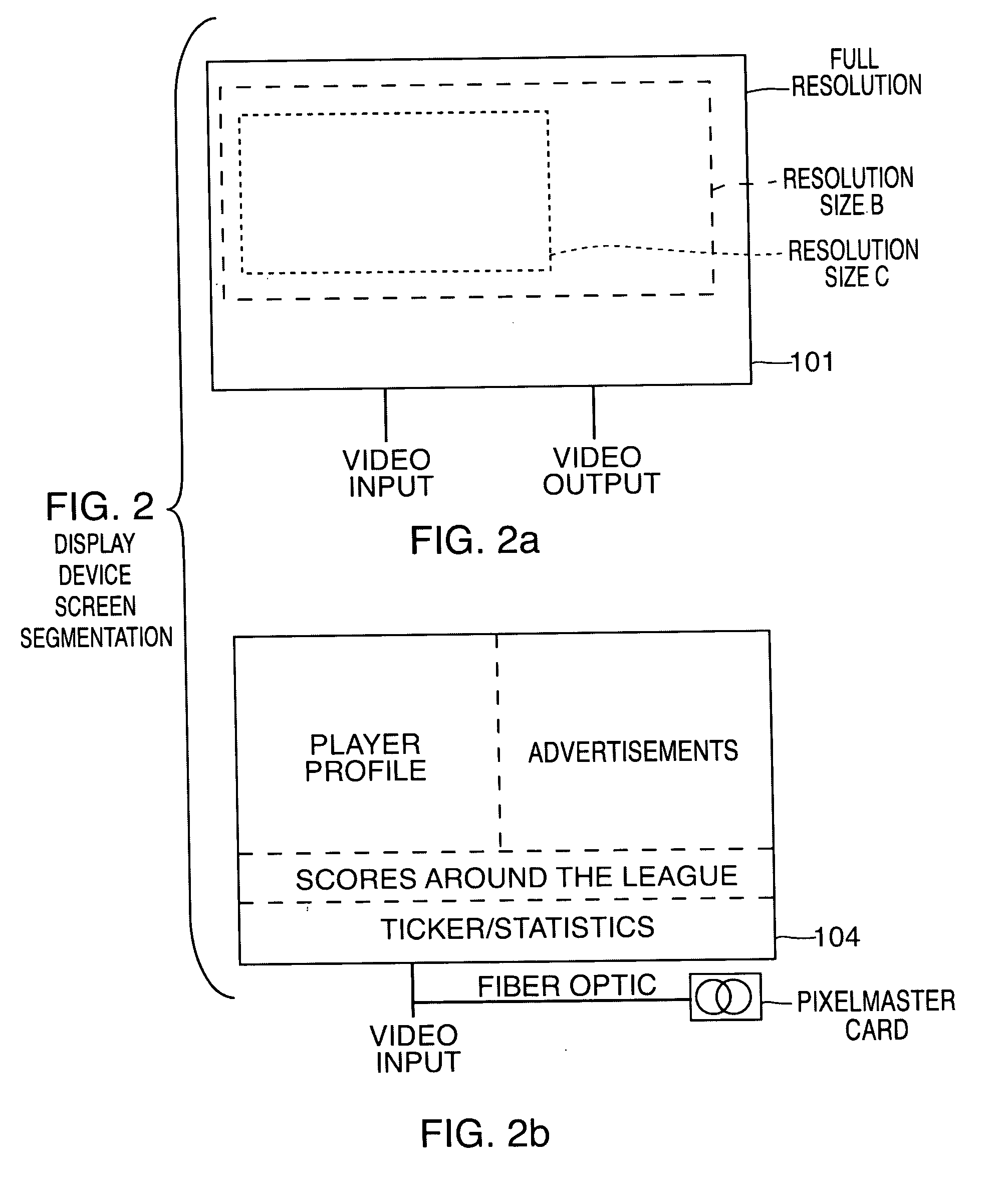
[0013]There is no compromise to image or video quality. In accordance with the invention, a dedicated GPU processes images using 3D acceleration to composite and render multiple layers, as opposed to strips in the older technologies. With the content items organized by the resolution length (or size) of the target display, the Sub-Servers can render the content items to their target display devices more efficiently.
[0014]With the graphics intensive processing operations distributed among hardware devices, an operator may take advantage of the adaptive and modular software design. The distributive flexibility of hardware and software across a network enables a number of users and applications to collaborate in the same virtual environment. Departing from the restrictive windows-based interface model, the current invention provides a seamless, real-time representation of display devices and the tools necessary to operate them.
[0015]A VUI gives an operator the advantage of managing pooled resources across the network, allowing them to be more responsive to dynamic needs and to better leverage entire infrastructure. The immersive 3-dimensional environment is capable of simultaneously presenting a graphical representation of every resource an operator may need. In a single environment, the VUI allows an operator to manage and control multiple display devices.
[0016]A VUI provides superior usability, enhanced user interaction and scalability. Usability is improved because the VUI gives an operator the freedom to move interface objects along the x, y as well as z-axis. The VUI makes learning an interface easier because it affords an operator broad latitude for display customizations, system configurations and plug-in possibilities. Scalability is a non-issue because is there is no limit to the number of display devices that can be managed. Even when the types of display technologies are different, the present invention gives the operator a fully dynamic three-dimensional representation of all the display devices on the network. With this approach, an operator may monitor and control playback on all of the display devices at the same time.

Problems solved by technology

The current technologies and systems available make that kind of seamless integration very difficult.
The wide array of media formats and the very specific requirements of display devices have unsurprisingly lead to a number of significant interoperability problems.
Interoperability problems force a display device operator to send video signals in a format that will be received by the video input of that display device and rendered correctly on the screen.
This may lead to a sacrifice in the quality of the content item and a waste of the processing resources.
There is no guarantee that these stand-alone tools will be able to convert every content item into a format that is displayable by every type of display device.
In addition, new formats for content are constantly being developed, making it more difficult to choose a standard.
Today's applications fall significantly short of this goal.
They are restricted by their design, a 2-dimensional window-based interface.
These window-based interfaces are limited to the amount of information that may be conveyed to an operator by the size of the monitor.
This results in “window thrashing,” in which the user must expend considerable effort to keep desired windows visible.
An operator may never be able to gain a perspective on how the system is doing as a whole without “thrashing.” Operating a second or third display device is nearly impossible with these interfaces.
The current windows-based interfaces used applications fail in providing adequate usability, interactivity and scalability.
The windows-based system fails because it requires an operator to toggle through windows to find the appropriate GUI for a particular task.
When a number of windows are open, the desktop becomes very cluttered making it very difficult for the user to interact with the application efficiently.
For the same reason, the multi-window design makes it impossible to scale.
It does not provide real-time video preview and control of what is being played on the display devices.
Thus, when the location of a physical display device is not within the operator's view, there is no way for the operator to monitor the performance of that display.

Method used


Image

  • Virtual interface and system for controlling a device
  • Virtual interface and system for controlling a device
  • Virtual interface and system for controlling a device

Examples


first embodiment

of Network Architecture

[0057]Turning now to FIG. 5, we see one example of how an embodiment of the invention may be configured on a network. In FIG. 5, the system's hardware devices are distributed across one Main Server 301, three Sub-Servers, and a network switch 302 and connected via Gigabit Ethernet. The system hardware sends a video signal to a router 303 that sends the signal to the video input 304 (processors) of the display devices 305. In the embodiment of FIG. 5, there are two display devices, an LED and a GIP Sideline display. The LED is broken up into four quadrants while the GIP Sideline display is broken up into two strips. FIG. 5 also shows a primary operator location having a monitor, mouse and keyboard. All of the hardware in FIG. 5 is operably connected to the network via DVI, DVI and USB, fiber optic cable, GBit Ethernet, or wireless internet (WAN).

second embodiment

of Network Architecture

[0058]Turning now to FIG. 6, we see a second example of how an embodiment of the invention may be configured on a network. In FIG. 6, the hardware is distributed across two Main Servers 401 having three monitors 402, keyboard 403 and mouse extender 403. The two Main Servers 401 are connected via Ethernet and router 404 to three Content (Render) servers, a VisionSoft (Main) server, a Statistics Server, and two Backup servers. The three Content (Render) Servers have their own GPUs and are connected to six medium sized display devices. The medium display devices include the SmartVision 15 mm Upper Ring, SmartVision 15 mm Stats, Mitsubishi 10 mm Video Display, SmartVision 15 mm Lower Ring, a first SmartVision 20 mm suite fascia, and a second SmartVision 20 mm suite one fascia. The VisionSoft (Main) Server has a GPU and is connected to a large display, the SmartVision outdoor video display. The Main server uses two monitors for controlling and managing the six medi...

third embodiment

of Network Architecture

[0059]Turning now to FIG. 7, we see yet another example of how an embodiment of the invention may be configured on a network. In FIG. 7, the hardware is distributed across three Main Servers having four monitors and two sets of input devices. The three Main Servers are connected via Ethernet and router to a Backup Server, Main Server workstation, having a monitor and input device, three Content (Render) Servers, and a sports ticker scoring system feed (Statistics Server). The three Content (Render) Servers are connected to four display devices processors via a fiber optic link. As shown in FIG. 7, the GPUs may transmit content items to the seven display devices via a dedicated feed, a plurality of content feeds, or both. The SmartVision 20 mm Upper Ring display receives a dedicated feed. A first and second SmartVision16.5 mm display device, which can provide 8 virtual scoring panels, receive a total of 8 content feeds, 4 content feeds a piece. A center hung vi...


PUM


Abstract

This invention relates to a system and method for operating and managing real world devices through a three-dimensional virtual user interface. In a preferred form, the invention relates to using a three-dimensional virtual user interface to control the playing of content items on a display device or on multiple display devices, all managed and operated by the present invention. The system allows for real-time previewing of the content items rendered on the displays on a single control computer monitor. The invention may be seen as a computer having an application employing a three-dimensional virtual user interface for operating and previewing a display device or devices.

Description

BACKGROUND OF THE INVENTION[0001]1. Field of the Invention[0002]This invention relates to a system and method for controlling and managing at least one device. The preferred implementation of this invention comprises a computer having a software application with a three-dimensional Virtual User Interface (VUI) for managing and controlling the rendering of content items to a display device or devices. These embodiments are particularly useful for operating signage displays in large arenas.[0003]2. Description of Related Art[0004]The advancement of display technologies has improved our ability to communicate information in a more effective and engaging way. High resolution in images and videos combined with relevant computer graphics allow for more enjoyable and contextual content. Incorporating live data feeds on a display device can provide an audience with real time information or statistical data regarding concurrent events and conditions. All of these content items can be strikin...

Claims


Application Information

Patent Timeline
IPC IPC(8): G06F3/048
CPCG06F3/0481G06F3/14H04L67/125H04L41/22G06F3/1423H04L41/40
Inventor STROSS, MARK
Owner STROSS MARK
Learn More