High-z structure and method for co-alignment of mixed optical and electron beam lithographic fabrication levels

a technology of electron beam lithography and high-z structure, which is applied in the field of semiconductor processing, can solve the problems of slow electron beam lithography, inability to print images on very small pitches, and inability to achieve the benefits of merging these two technologies

Inactive Publication Date: 2008-07-03
TAIWAN SEMICON MFG CO LTD
View PDF8 Cites 11 Cited by
  • Summary
  • Abstract
  • Description
  • Claims
  • Application Information

AI Technical Summary

Problems solved by technology

In general, optical lithography is fast but cannot print images on very small pitches.
Electron beam lithography can print images on very small pitches, but is slow.
The benefits derivable from merging of these two technologies is hindered by the fact that electron beam lithographic systems cannot register to current optical alignment structures.

Method used


Image

  • High-z structure and method for co-alignment of mixed optical and electron beam lithographic fabrication levels
  • High-z structure and method for co-alignment of mixed optical and electron beam lithographic fabrication levels
  • High-z structure and method for co-alignment of mixed optical and electron beam lithographic fabrication levels

Examples


Embodiment Construction

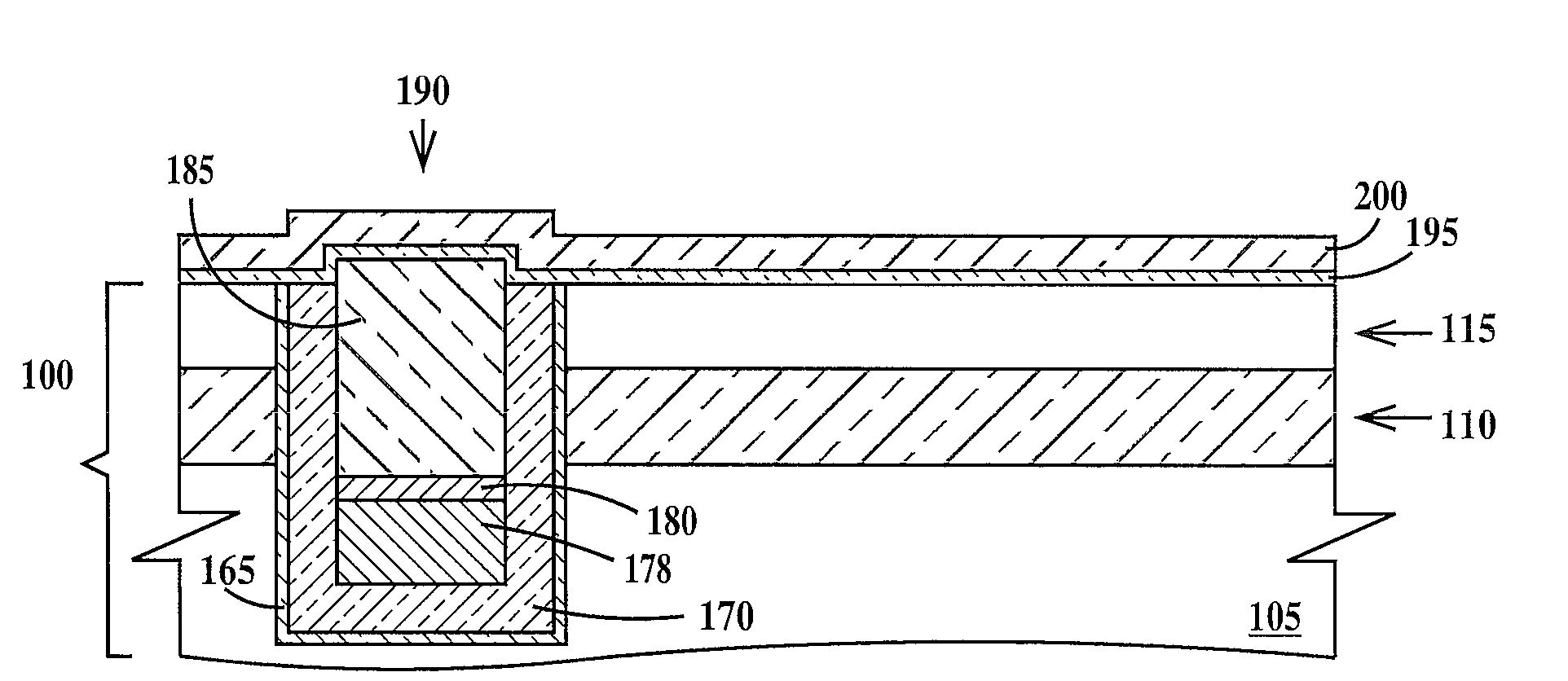
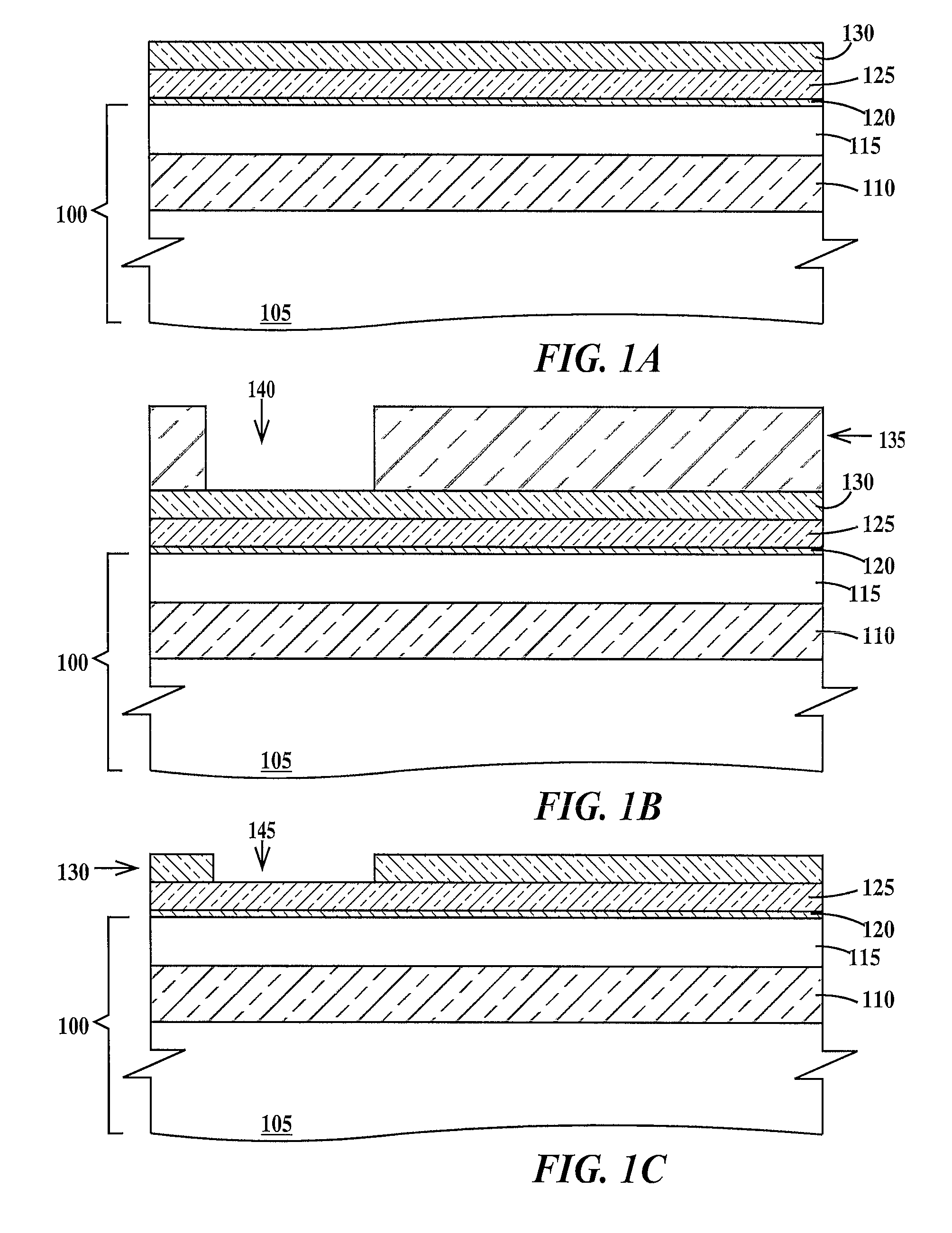
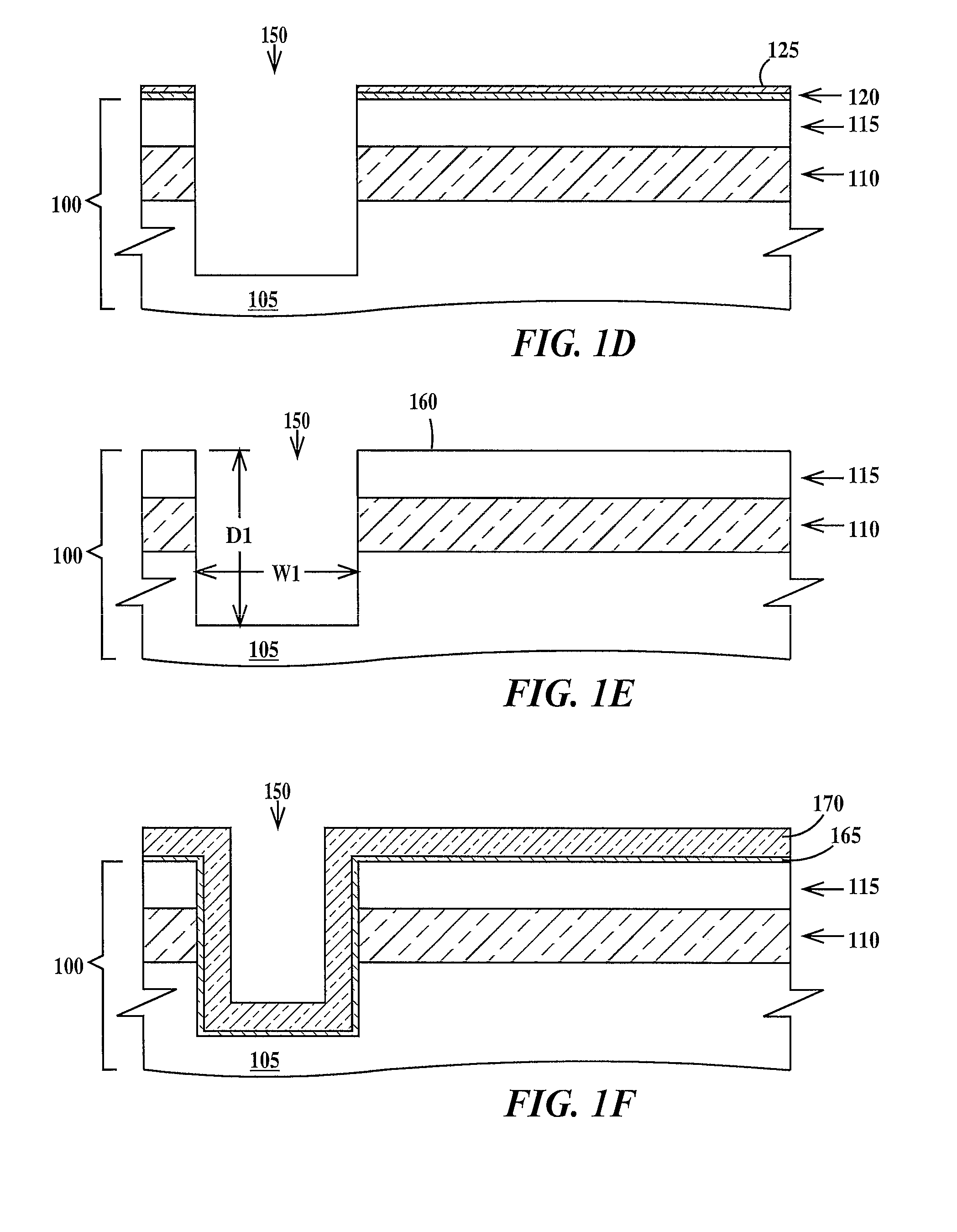
[0017]Lithographic alignment is defined as the process of positioning different structures of an integrated circuit in horizontal directions (e.g. x-y position) with respect to each other and to a substrate on which the integrated circuit is being formed. A horizontal direction is defined as any direction parallel to the top surface of the substrate. A fabrication level of an integrated circuit is defined as a level that images a group of related patterned structures of the integrated circuit that are to be formed simultaneously in or on the substrate. A fabrication level may include two or more lithographic steps.

[0018]Optical lithography (herein after photolithography) forms a pattern of resist features and spaces in a resist layer by exposure of the resist layer to actinic radiation (e.g. ultraviolet light) through a photomask having a corresponding pattern of clear and opaque (to the actinic radiation) regions. Photolithographic alignment relies on positioning an image of an ali...


PUM

PropertyMeasurementUnit
thicknessaaaaaaaaaa
thicknessaaaaaaaaaa
thickaaaaaaaaaa

Abstract

A method for aligning a first set of features of a fabrication level of an integrated circuit chip to an electron beam alignment target including a high atomic weight layer formed in a substrate and forming the first set of features using electron beam lithography and for aligning a second set of features of the same fabrication level of the integrated circuit chip to an optical alignment target formed in the substrate and forming the second set of features using photolithography, the optical alignment target itself is aligned to the electron beam alignment target. Also a method of forming and a structure of the electron beam alignment target.

Description

FIELD OF THE INVENTION[0001]The present invention relates to the field of semiconductor processing; more specifically, it relates to an alignment target and a method for co-alignment of mixed optical and electron beam lithographic fabrication levels.BACKGROUND OF THE INVENTION[0002]In order to fabricate an integrated circuit the various lithographically defined fabrications levels must be aligned to each other. In optical lithography, a layer of photoresist on a substrate is exposed to actinic radiation through a patterned photomask that is aligned to an alignment target on the substrate. Structures fabricated in earlier lithographic fabrication steps serve as these alignment targets for alignment marks on the photomasks. Electron beam lithography, by contrast is a direct-write process, there are no photomasks and the electron beam is scanned across an electron beam resist layer. For each fabrication level, the electron beam must be registered to a reference structure. In general, o...

Claims


Application Information

Patent Timeline
Patent Type & Authority Applications(United States)
IPC IPC(8): H01L23/544G03F7/20H01L21/76
CPCB82Y10/00B82Y40/00H01L2924/0002H01J37/3174H01L21/76283H01L21/823481H01L21/84H01L23/544H01L2223/54426H01L2223/54453G03F7/7045G03F9/7076G03F9/708G03F9/7088H01L2924/00G03F7/70466G03F9/7073
Inventor FRIED, DAVID MICHAELHERGENROTHER, JOHN MICHAELMCNAB, SHAREE JANEROOKS, MICHAEL J.TOPOL, ANNA
Owner TAIWAN SEMICON MFG CO LTD
Why Eureka
Try Eureka