Sound Absorbing Material and Structure Using the Same

a technology structure, applied in the direction of instruments, walls, flooring, etc., can solve the problems of not achieving sufficient sound absorbing effect, heavy weight of sound absorbing material, and needing to widen the spa

Inactive Publication Date: 2008-07-10
SWCC SHOWA DEVICE TECHNOLOGY CO LTD
View PDF42 Cites 8 Cited by
  • Summary
  • Abstract
  • Description
  • Claims
  • Application Information

AI Technical Summary

Benefits of technology

[0033]According to the sound absorbing material and the structure using the same form the first feature to the eighteenth feature of this invention, there are following effects.
[0034]First, because the flame retardancy which fits the standard of the flame retardancy of the Building Standard Law is given to the sound absorbing material itself, this sound absorbing material can be arranged in the place where the flame retardancy is needed.
[0035]Second, because neither the halogen system flame retardant nor the lead c is used as the flame retardant, there is no fear that the noxious fume is generated during combustion. And the sound absorbing material that the environmental preservation measures was given can be provided.
[0036]Third, according to the sound absorbing material and the structure using the same which has the porous layer in both sides of the film, the noise of high-frequency band beyond 200 Hz as well as low-frequency band of 200 Hz or less can be absorbed effectively.
[0037]Fourth, according to the sound absorbing material and the structure using the same that the film is integrated with the porous layer, the degree of freed of the product form can be i=proved.BRIEF DESCRIPTION OF THE FIGURES
[0038][FIG. 1] The sectional view of the sound absorbing material and the structure using the same in the first embodiment of this invention.

Problems solved by technology

Consequently, there was a difficult point that the weight of the sound absorbing material becomes heavy.
And, in the sound absorbing materials of (c), because there is the air layer in the sound source side of the sound absorbing material, there were difficult points that the weight of the sound absorbing material became heavy and it was necessary to widen the space.
Regarding the sound absorbing material of this kind of structure, there was a difficult point that the sufficient sound absorbing effect is not obtained in so-called low-frequency band of 100 Hz or less especially.
Therefore, it was difficult to take the prevention measures about the sound absorbing material known in the conventional technology.
However, in the sound absorbing material of this kind of structure, there were following difficult points.
First, because the flame retardancy is not given to the sound absorbing material itself, this sound absorbing material does not fit the standard of the flame retardancy of the Building Standard Law.
Second, in the glass wool which composes the porous layer, the sound absorbing effect becomes weak in the high-frequency band beyond 200 Hz or in the low-frequency band of 200 Hz or less.
Third, because the foam layer and the porous layer are composed individually, the construction on the site becomes complicated.

Method used


Image

  • Sound Absorbing Material and Structure Using the Same
  • Sound Absorbing Material and Structure Using the Same
  • Sound Absorbing Material and Structure Using the Same

Examples


first embodiment

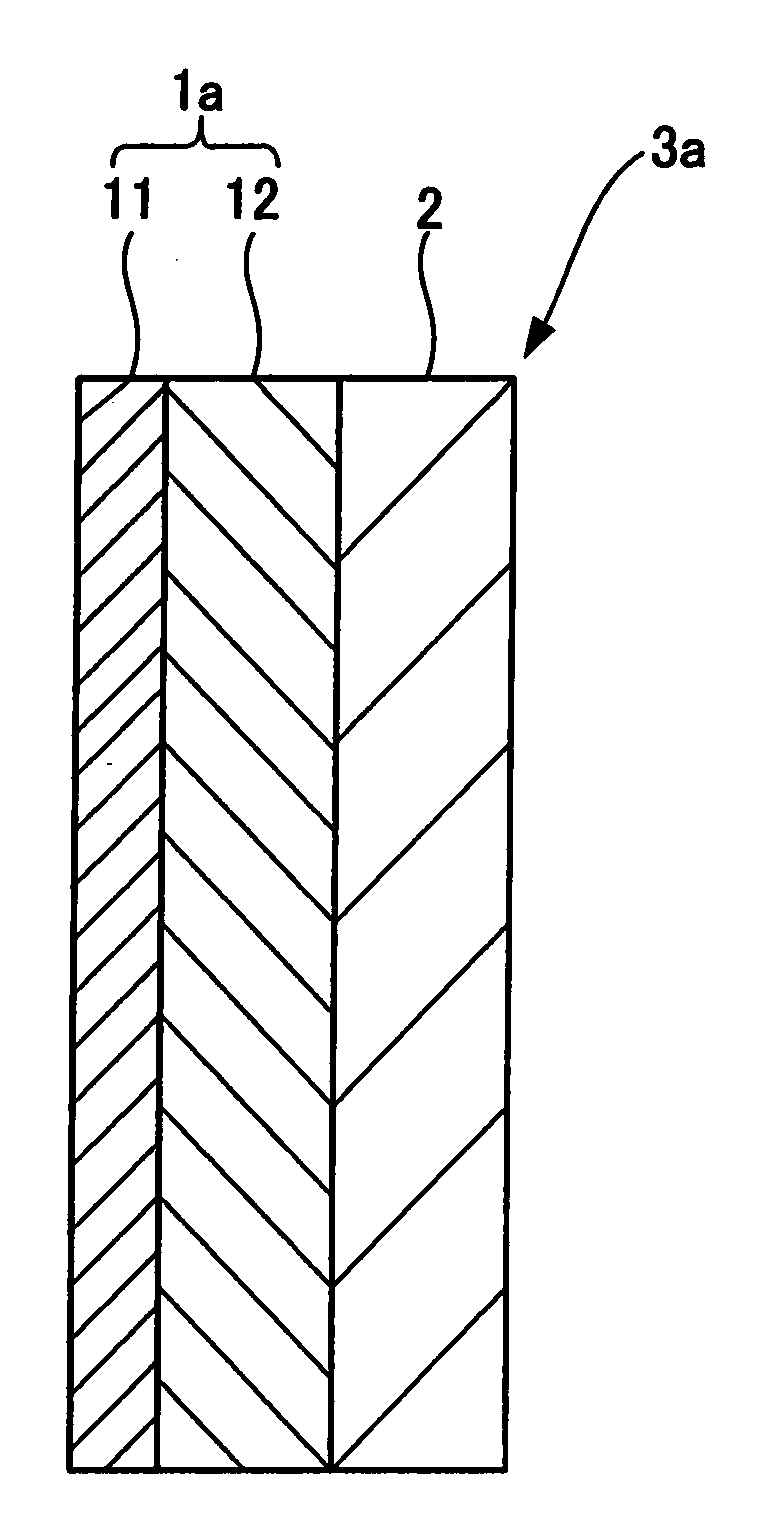
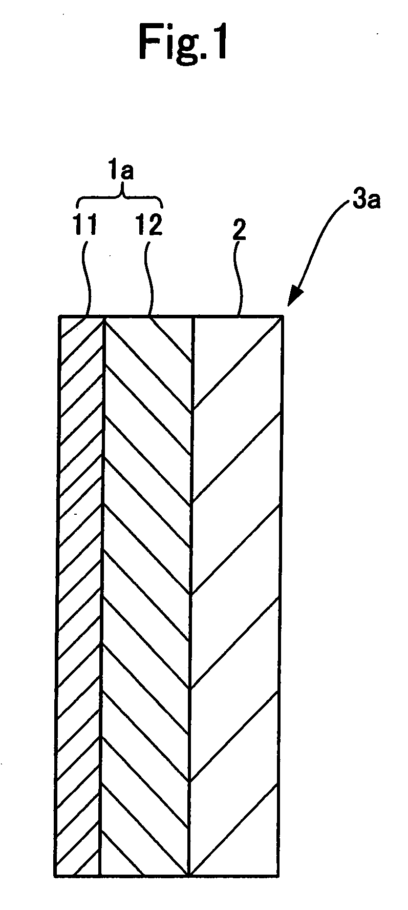
[0048]FIG. 1 is the sectional view which shows the first embodiment of this invention using the sound absorbing material and the structure using the same.

[0049]In this figure, the sound absorbing material 1a of this invention comprises the film 11 composed of the silicone rubber and the porous layer 12 (hereinafter called, “first porous layer”) which is laminated on the back surface of the film 11. Here, the reason to laminate the first porous layer 12 on the back surface of the film 11 composed of the silicone rubber is that the film 11 acts as the mass, that is, the role of the weight, and the first porous layer 12 acts as spring, that is, the role of the air spring, and the sound absorption is performed by membrane vibration.

[0050]In such the sound absorbing material 1a, for a rigid wall 2, by making the first porous layer 12 face the rigid wall 2, and by arranging such the sound absorbing material 1a in parallel with the rigid wall 2, a structure 3a of this invention can be form...

second embodiment

[0068]FIG. 4 shows the sectional view of the structure of the filmy sound absorbing structure which used the sound absorbing material 1a of the first embodiment. Meanwhile, in this figure, the same reference numbers are given to the portions which are common to FIG. 1, and detailed explanation is omitted.

[0069]In FIG. 4, the structure 3b of this invention comprises the rigid wall 2, and the filmy (thickness: about 0.5 mm) sound absorbing material 1a that the first porous layer 12 faces the rigid wall 2 and which is arranged on the sound source side of the rigid wall 2 in parallel with the rigid wall 2 through a pair of supporting members 4a, 4b, and the back air layer 5 which is sectioned between the sound absorbing material 1a and the rigid wall 2.

[0070]In the structure 3b of the filmy sound absorbing structure of such composition, because the back air layer 5 acts as the spring to the mass of the filmy sound absorbing material 1a, the single resonance system is formed. And, when t...

third embodiment

[0071]FIG. 5 shows the sectional view of the structure which applied the sound absorbing material 1a to the sound insulation wall of the first embodiment. Meanwhile, in this figure, the same reference numbers are given to the portions which are common to FIG. 1, and detailed explanation is omitted.

[0072]In FIG. 5, the structure 3c of this invention has the hollow double wall 6 which is placed as the simplified partition, for example on the floor inside the building.

[0073]The hollow double wall 6 comprises the first wall member 6a which is arranged in the sound source side, and the second wall member 6b which is arranged in parallel with the first wall member 6a at the position where predefined length was estranged from the first wall member 6a in the sound receiving side. And, the aforementioned sound absorbing material 1a is arranged in parallel with the first wall member 6a (or the second wall member 6b) between these first and second wall members 6a, 6b.

[0074]According to the st...


PUM

PropertyMeasurementUnit
frequencyaaaaaaaaaa
frequencyaaaaaaaaaa
frequencyaaaaaaaaaa

Abstract

A sound absorbing material (1a) comprising a film (11) composed of a silicone rubber and a porous layer (12) (i.e., a first porous layer) laminated on the back surface of the film (11). The film (11) is made of a material which has flame retardancy and generates no noxious fume during combustion, such as a silicone rubber comprising only polysiloxane. The film (11) used is preferably one which has an oxygen index of 25 or higher, which exhibits a heat release value of combustion per unit volume of 8 MJ / m or less and which exhibits a heat release rate of combustion of [200 kW / m2]·10 sec or less. The first porous layer (12) is formed from a material having flame retardancy, such as glass wool, rock wool or a mixture thereof. A structure (3a) can be formed by providing the sound absorbing material (1a) having the construction described above on a rigid wall (2) in parallel, with the first porous layer (12) facing to the rigid wall (2).

Description

TECHNICAL FIELD[0001]This invention relates to a sound absorbing material and a structure using the same. In particular, this invention relates to the sound absorbing material and the structure using the same which absorbs noise of high-frequency band beyond 200 Hz as well as low-frequency band of 200 Hz or less effectively and can improve the degree of freedom of the product form.[0002]Heretofore, as the sound absorbing material of this kind, (a) the thing which uses a porous layer comprising a glass wool or a rock wool, and so on; (b) the thing which has an air layer in the sound source side; (c) the thing which has an air layer in the sound source side of the sound absorbing material; (d) the thing which laminates the aggregates of the high density and low density fibers more than at least two layers that the air permeability are different approximately 5-100 times; are known (for example, refer to patent document No. 1).[0003]However, in the sound absorbing materials of (a) and ...

Claims


Application Information

Patent Timeline
Patent Type & Authority Applications(United States)
IPC IPC(8): E04B2/02E04B1/84
CPCB32B5/18B32B25/20E01F8/0005G10K11/168E04B1/86E04B2001/8461E01F8/0029
Inventor HIRAI, SUSUMUOKASHITA, MINORUKOBAYASHI, HIROKIKITAMURA, TASUKU
Owner SWCC SHOWA DEVICE TECHNOLOGY CO LTD
Why Eureka
Try Eureka