Cascaded Organic Rankine Cycles for Waste Heat Utilization

a rankine cycle and organic technology, applied in steam engine plants, machines/engines, mechanical equipment, etc., can solve the problems of system, although very cost-effective, not fully taking advantage of the thermodynamic potential of waste heat streams, and achieves substantial reduction of waste heat loss to the atmosphere and greater efficiency

Inactive Publication Date: 2008-07-17
INT FUEL CELLS
View PDF11 Cites 70 Cited by
  • Summary
  • Abstract
  • Description
  • Claims
  • Application Information

AI Technical Summary

Benefits of technology

[0007]By another aspect of the invention, the refrigerants of the two systems are chosen such that the condensation temperature of the first, higher temperature, system is a useable temperature for boiling the refrigerant of the second, lower temperature, system. In this way, greater efficiencies may be obtained and the waste heat loss to the atmosphere is substantially reduced.

Problems solved by technology

However, atmospheric emissions such as nitrogen oxides (NOx) and particulates can be a problem with reciprocating engines.
However these systems, although very cost-effective, do not take full advantage of the thermodynamic potential of the waste heat stream.

Method used


Image

  • Cascaded Organic Rankine Cycles for Waste Heat Utilization
  • Cascaded Organic Rankine Cycles for Waste Heat Utilization
  • Cascaded Organic Rankine Cycles for Waste Heat Utilization

Examples


Embodiment Construction

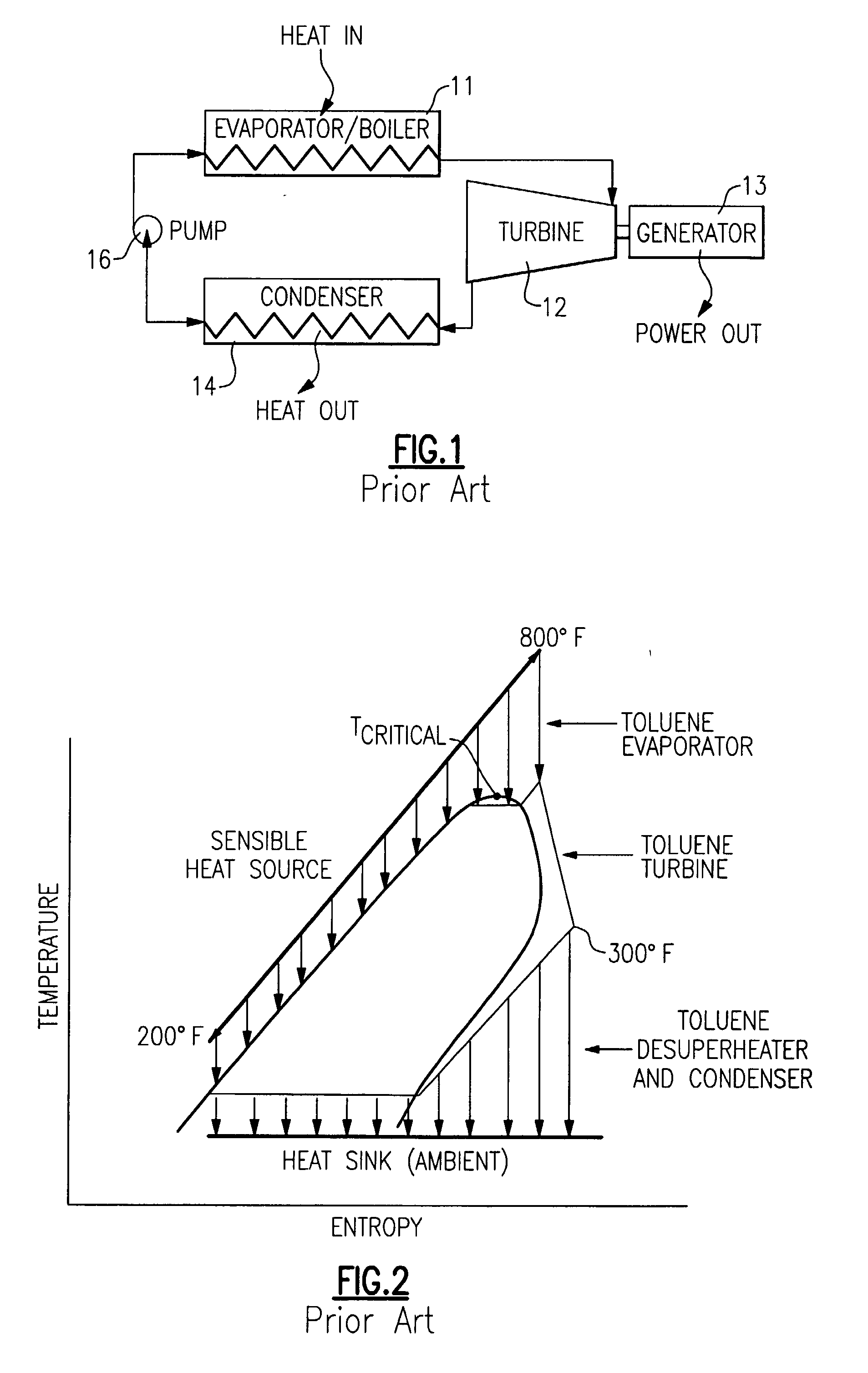
[0020]Referring now to FIG. 1, a conventional type of organic Rankine cycle system is shown to include an evaporator / boiler 11 which receives waste heat from a source as described hereinabove. The heated working fluid passes to the turbine 12, where it is converted to motive power to drive a generator 13. The resulting lower temperature and pressure working fluid then passes to a condenser 14 where it is converted to a liquid, which is then pumped by the pump 16 back to the evaporator / boiler 11.

[0021]In such a typical system, a common working fluid is toluene. In the vapor generator 11 the working fluid has its temperature raised to around 525° F. after which it is passed to the turbine 12. After passing through the turbine 12, the temperature of the vapor drops down to about 300° F. before it is condensed and then pumped back to the evaporator / boiler 11.

[0022]Shown in FIG. 2 is a TS diagram of the organic rankine cycle system illustrated in FIG. 1, using toluene as the working flui...


PUM


Abstract

A pair of organic Rankine cycle systems (20, 25) are combined and their respective organic working fluids are chosen such that the organic working fluid of the first organic Rankine cycle is condensed at a condensation temperature that is well above the boiling point of the organic working fluid of the second organic Rankine style system, and a single common heat exchanger (23) is used for both the condenser of the first organic Rankine cycle system and the evaporator of the second organic Rankine cycle system. A preferred organic working fluid of the first system is toluene and that of the second organic working fluid is R245fa.

Description

STATEMENT OF GOVERNMENT INTEREST[0001]The United States Government has certain rights in this invention pursuant to Contract No. DE-FC02-00CH11060 between the Department of Energy and United Technologies Corporation.BACKGROUND OF THE INVENTION[0002]Power generation systems that provide low cost energy with minimum environmental impact, and that can be readily integrated into the existing power grids or rapidly sited as stand-alone units, can help solve critical power needs in many areas. Combustion engines such as microturbines or reciprocating engines can generate electricity at low cost with efficiencies of 25% to 40% using commonly available fuels such as gasoline, natural gas and diesel fuel. However, atmospheric emissions such as nitrogen oxides (NOx) and particulates can be a problem with reciprocating engines.[0003]One method to generate electricity from the waste heat of a combustion engine without increasing the output of emissions is to apply a bottoming cycle. Bottoming c...

Claims


Application Information

Patent Timeline
Patent Type & Authority Applications(United States)
IPC IPC(8): F01K13/00F01K25/08
CPCF01K25/08F01K23/04
Inventor RADCLIFF, THOMAS D.BIEDERMAN, BRUCE P.BRASZ, JOOST J.
Owner INT FUEL CELLS
Why Eureka
Try Eureka