Apparatus and method for deep groove welding

a deep groove and welding apparatus technology, applied in the field of deep groove welding, can solve the problems of unsuitable applications, twin wire welding in close proximity, unsuitable for and incompatibility of twin wire welding torches with narrow deep grooves, so as to increase welding speed and increase welding speed

Inactive Publication Date: 2008-07-17
GENERAL ELECTRIC CO
View PDF22 Cites 16 Cited by
  • Summary
  • Abstract
  • Description
  • Claims
  • Application Information

AI Technical Summary

Benefits of technology

[0006]Another embodiment of the invention includes a method of increasing welding speed using a welding apparatus having a torch body with at least one core, a plurality of contact tips extending in a first direction from the at least one core, and a plurality of gas supply tubes disposed proximate the plurality of contact tips, the gas supply tubes extending in a substantially similar direction as the plurality of contact tips. The method includes defining at least one of the plurality of contact tips as a leading contact tip and at least one other of the plurality of contact tips as a trailing contact tip, moving the welding apparatus in a second direction, and controlling at least one of the leading contact tip and the trailing contact tip independent of the other to increase welding speed.

Problems solved by technology

However, excessive heat generation, resulting from the corresponding increase in current, can lead to undesired distortion of the workpiece.
However, twin wire welding in close proximity, using a single conventional power supply, is unsuitable for applications such as deep narrow groove welding due to instability of the arc, metal transfer associated with interaction of adjacent magnetic fields, and variations in an energy of the arc corresponding to each wire electrode.
Prior attempts to provide process requirements of wire electrode cooling and delivery of the shielding gas have resulted in twin wire welding torches that are not compatible with narrow deep grooves, such as those used in the production of steam turbine components, for example.

Method used


Image

  • Apparatus and method for deep groove welding
  • Apparatus and method for deep groove welding
  • Apparatus and method for deep groove welding

Examples


Embodiment Construction

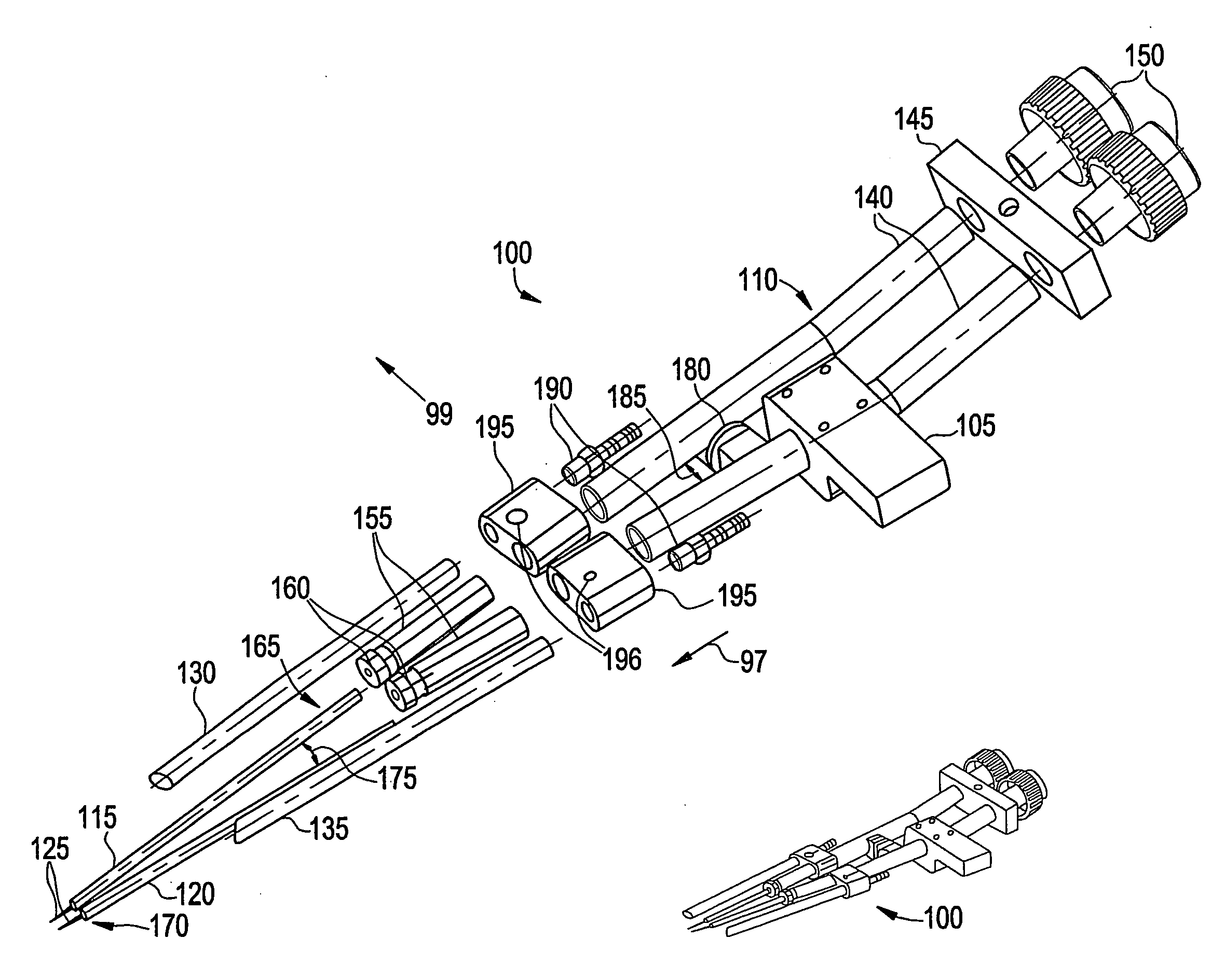
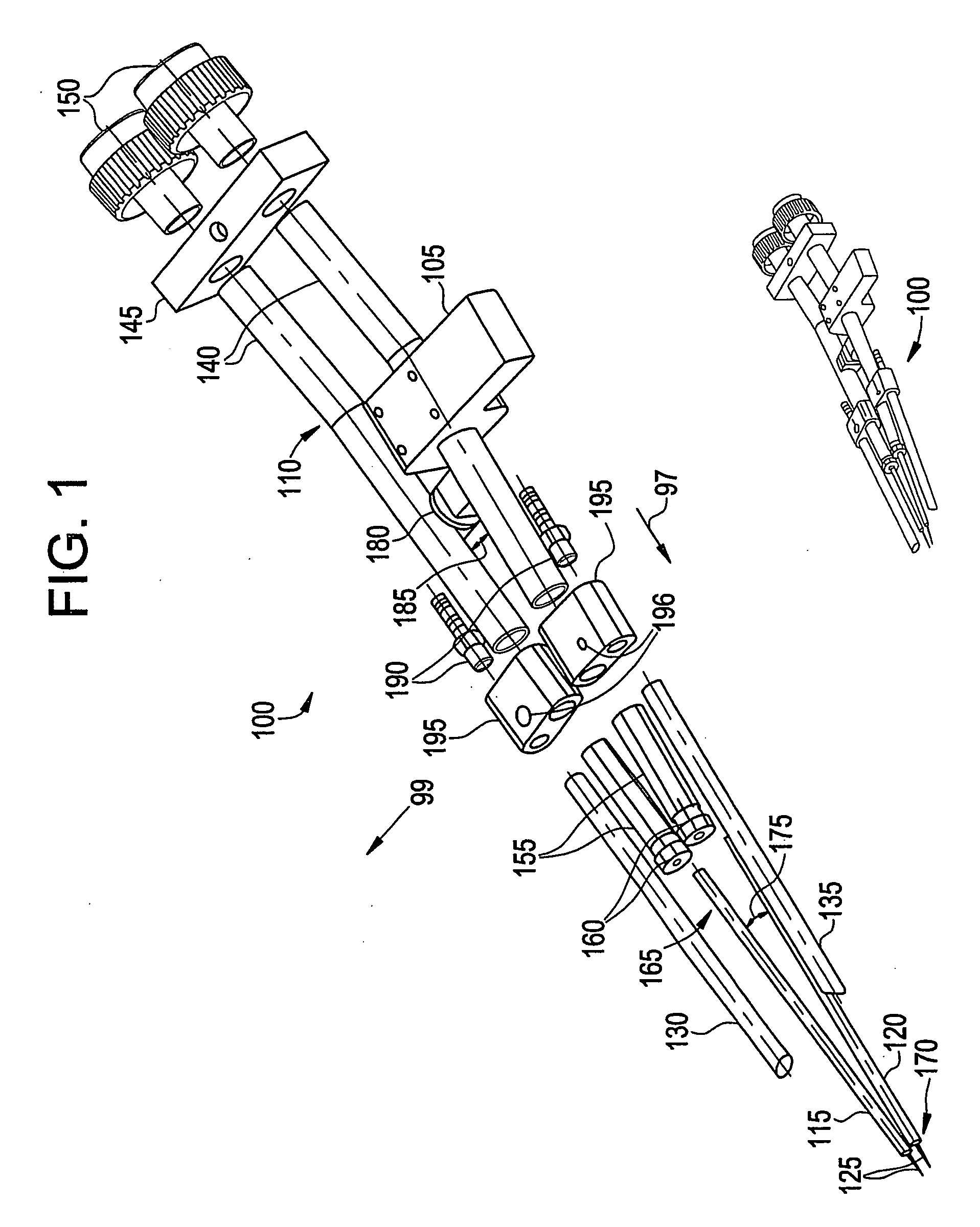
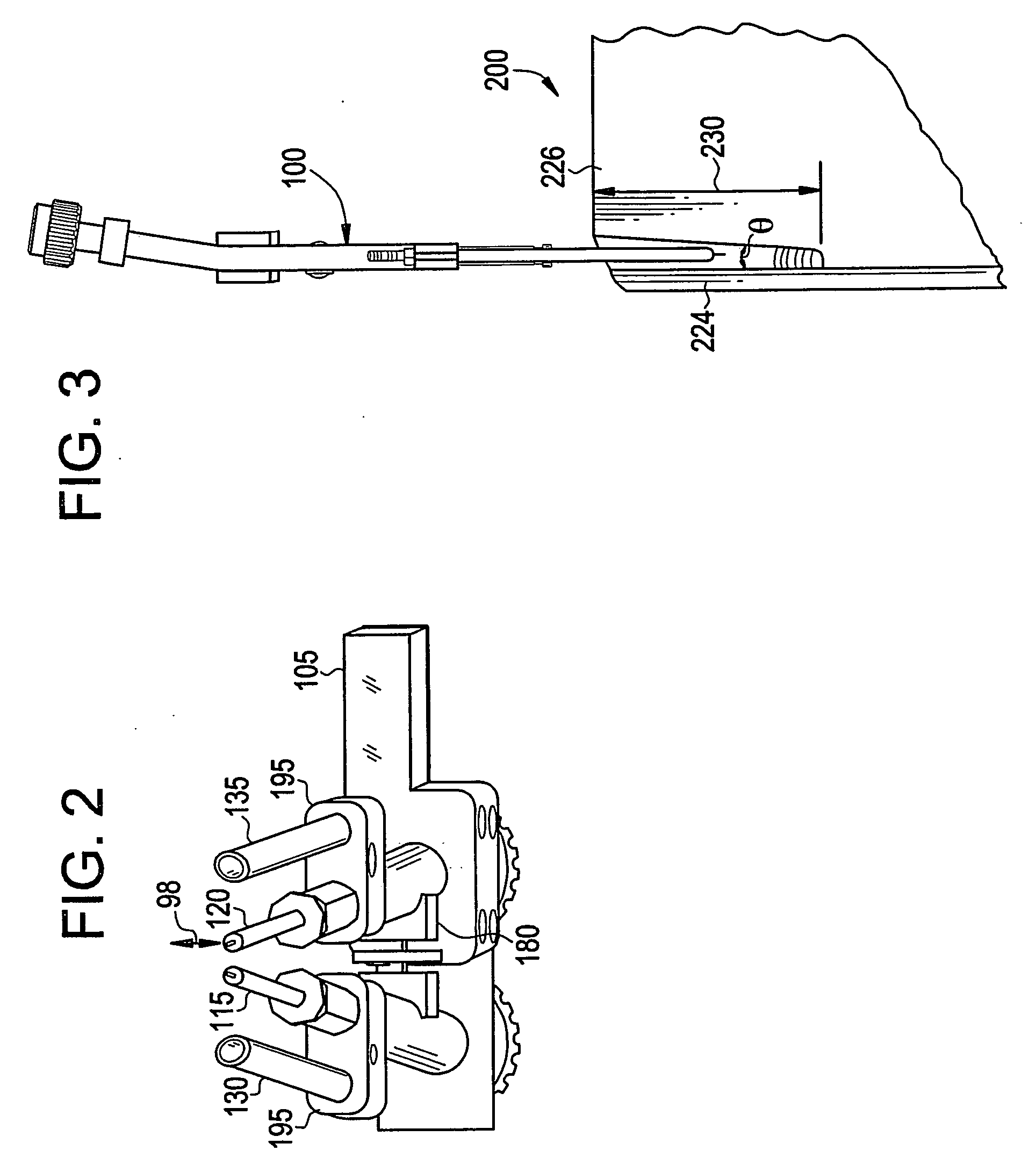
[0012]An embodiment of the invention will provide a torch and a process for narrow groove MIG welding using two wire electrodes fed into a common molten pool of weld material. The torch is capable of operation in a narrow groove to reduce required welding time compared to presently used single wire electrode MIG welding systems. In an embodiment, the process facilitates improved welding productivity due to higher welding speeds and higher deposition rates of the wire electrodes. In an embodiment, each wire electrode is connected to its own power supply to enable independent adjustment of a welding voltage, a current level, and a welding power delivery waveform, such as continuous or pulse modulated power delivery waveforms, for example.

[0013]In an embodiment, a composition of deposited metal can be customized by independently varying at least one of a wire electrode diameter, alloy content, and feed rate for each of two separate contact tips, to result in improved metallurgical and ...


PUM

PropertyMeasurementUnit
groove angleaaaaaaaaaa
angleaaaaaaaaaa
diameteraaaaaaaaaa

Abstract

A welding apparatus is disclosed. The welding apparatus includes a torch body comprising at least one core, a plurality of contact tips extending in a direction from the at least one core, and a plurality of gas supply tubes disposed proximate the plurality of contact tips, the plurality of gas supply tubes extending in a substantially similar direction as the plurality of contact tips.

Description

BACKGROUND OF THE INVENTION[0001]The present disclosure relates generally to welding, and particularly to deep groove welding.[0002]Gas metal arc welding, including metal inert gas (MIG) welding employs a consumable wire electrode, also herein referred to as a wire electrode, an electrical supply, and a system for directing a shielding gas to a weld area. The wire electrode and the shielding gas are continuously fed through a “torch” in electrical connection with the electrical supply into the weld area. A workpiece is connected by an earth lead that completes a circuit with the electrical supply. The wire electrode is held at a potential above ground using a power source capable of supplying an appropriate amount of current to produce an arc. When the wire electrode touches the workpiece, the arc is formed, which melts localized metal of the workpiece and the wire electrode, forming a molten pool, which subsequently cools to form a weld. The shielding gas protects the molten pool f...

Claims


Application Information

Patent Timeline
Patent Type & Authority Applications(United States)
IPC IPC(8): B23K5/00B23K31/02
CPCB23K9/0213B23K9/1735B23K9/124B23K9/16B23K9/173B23K9/26B23K9/32
Inventor SPIEGEL, LYLE B.ELLIS, EDWARD KENNETHCHILDS, WILLIAM HAROLDBURKE, PETER ROBERT
Owner GENERAL ELECTRIC CO
Why Eureka
Try Eureka