Carbide derived carbon, emitter for cold cathode including the same and electron emission device including the emitter

a carbon and carbide technology, applied in the manufacture of electric discharge tubes/lamps, discharge tubes luminescnet screens, electrode systems, etc., can solve the problems of fiber type carbon nanotube materials with many problems, short lifetime, and poor uniformity, and achieve good uniformity and long lifetime

Inactive Publication Date: 2008-07-17
LOFFE PHYSICO TECHN INST OF RUSSIAN ACADEMY OF SCI +1
View PDF3 Cites 20 Cited by
  • Summary
  • Abstract
  • Description
  • Claims
  • Application Information

AI Technical Summary

Benefits of technology

[0014]Aspects of the present invention provide carbide derived carbon that can be prepared using a more inexpensive method than that used to manufacture conventional carbon nanotubes where the nanotubes have good uniformity and a long lifetime, an emitter for cold cathodes including the carbide derived carbon and an electron emission device including the emitter.

Problems solved by technology

Fiber type carbon nanotube materials have many problems such as bad uniformity, a short lifetime, and the like.
When fiber type carbon nanotubes are manufactured using paste, ink, slurry, or the like, manufacturing problems occur compared with other materials in particle form.
In addition, the raw materials are too expensive.

Method used


Image

  • Carbide derived carbon, emitter for cold cathode including the same and electron emission device including the emitter
  • Carbide derived carbon, emitter for cold cathode including the same and electron emission device including the emitter
  • Carbide derived carbon, emitter for cold cathode including the same and electron emission device including the emitter

Examples


example 1

[0062]First, as a carbon precursor, 100 g of particulate α-SiC with the particles having a mean diameter of 0.7 μm were prepared in a high temperature furnace composed of a graphite reaction chamber, a transformer, and the like. 0.5 l per minute of Cl2 gas were applied to the high temperature furnace held at 1000° C. for 7 hours. Then, 30 g of carbide derived carbon were prepared by extracting Si from the carbon precursor using a thermochemical reaction.

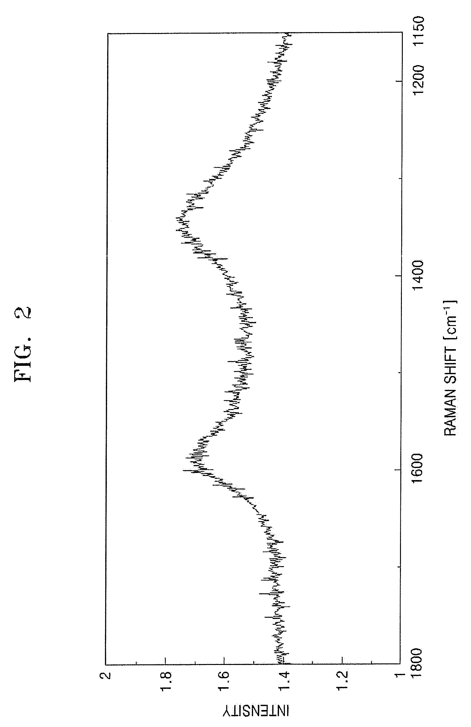
[0063]The carbide derived carbon was analyzed using Raman peak analysis, X-ray diffractometry and an electron microscope. The IG / ID ratio ranged from 0.5 through 1. A weak peak of the graphite (002) surface could be seen at 2θ=25°. The electron diffraction pattern was a halo-pattern typical of amorphous carbon. In addition, the specific surface area of the carbide derived carbon synthesized by this method ranged from 1000 through 1100 m2 / g according to the method of Brunauer, Emmett and Teller (BET method).

example 2

[0064]13 g of carbide derived carbon were prepared in the same manner as in Example 1 except that 100 g of particulate ZrC, with the particles having a mean diameter of 3 μm, were used as a starting carbide compound and were heat treated at 600° C. for 5 hours. The carbide derived carbon was analyzed using Raman peak analysis. The IG / ID ratio ranged from 1 through 1.3. A weak single peak of the graphite (002) surface could be seen at 2θ=25° using the X-ray diffractometry. In addition, the specific surface area of the carbide derived carbon synthesized by this method was 1200 m2 / g according to the BET method.

example 3

[0065]25 g of carbide derived carbon were prepared in the same manner as in Example 1 except that 100 g of particulate Al4C3, with the particles having a mean diameter of 3 μm, were used as a starting carbide compound and were heat treated at 700° C. for 5 hours. The carbide derived carbon was analyzed using Raman peak analysis and X-ray diffractometry. The IG / ID ratio ranged from 1 through 3.2. A weak single peak of the graphite (002) surface was seen at 2θ=25°. The carbide derived carbon was analyzed using high resolution TEM. Many graphite fringes could be seen, as illustrated in FIGS. 10 and 11. In addition, the specific surface area of the carbide derived carbon synthesized by this method ranged from 1050 through 1100 m2 / g according to the BET method.


PUM

PropertyMeasurementUnit
temperatureaaaaaaaaaa
mean diameteraaaaaaaaaa
temperatureaaaaaaaaaa

Abstract

Provided are carbide derived carbon prepared by thermochemically reacting carbide compounds and a halogen element containing gas and extracting all atoms of the carbide compounds except carbon atoms, wherein the intensity ratios of the graphite G band at 1590 cm−1 to the disordered-induced D band at 1350 cm−1 are in the range of 0.3 through 5 when the carbide derived carbon is analyzed using Raman peak analysis, wherein the BET surface area of the carbide derived carbon is 1000 m2/g or more, wherein a weak peak or wide single peak of the graphite (002) surface is seen at 2θ=25° when the carbide derived carbon is analyzed using X-ray diffractometry, and wherein the electron diffraction pattern of the carbide derived carbon is the halo pattern typical of amorphous carbon when the carbide derived carbon is analyzed using electron microscopy. The emitter has good uniformity and a long lifetime. An emitter can be prepared using a more inexpensive method than that used to manufacture conventional carbon nanotubes.

Description

CROSS-REFERENCE TO RELATED APPLICATIONS[0001]This application claims the benefit of Russian Patent Application No. 2006137605, filed on 24 Oct. 2006 in the Russian Patent Office, and Korean Patent Application No. 2006-126401, 126401, filed on 12 Dec. 2006 in the Korean Intellectual Property Office, the disclosures of which are incorporated herein in their entirety by reference.BACKGROUND OF THE INVENTION[0002]1. Field of the Invention[0003]Aspects of the present invention relate to carbide derived carbon, an emitter for cold cathodes including the carbide derived carbon and an electron emission device including the emitter; and more particularly, to carbide derived carbon that can be prepared using a more inexpensive method than that used to manufacture conventional carbon nanotubes where the nanotubes of the present invention have good uniformity and a long lifetime, an emitter for cold cathodes including the carbide derived carbon and an electron emission device including the emit...

Claims


Application Information

Patent Timeline
Patent Type & Authority Applications(United States)
IPC IPC(8): H01J1/62C01B31/02
CPCC01B31/02H01J2201/30446H01J9/025H01J1/304C01B32/05
Inventor KIM, YOON-JINZANG, DONG-SIKKIM, JAE-MYUNGMOON, HEE-SUNGGARIFOVICH, GABDULLIN PAVELNIKOLAYEVICH, DAVYDOV SERGEYVASILYEVICH, KORABLEV VADIMEFIMOVICH, KRAVCHIK ALEXANDERVASILYEVICH, SOKOLOV VASILYALEXANDROVNA, KUKUSHKINA YULIAFEDOROVICH, TERESHCHENKO GENNADY
Owner LOFFE PHYSICO TECHN INST OF RUSSIAN ACADEMY OF SCI
Why Eureka
Try Eureka