Eureka AIR delivers breakthrough ideas for toughest innovation challenges, trusted by R&D personnel around the world.

Color image forming apparatus and image forming method

Active Publication Date: 2008-07-24
KONICA MINOLTA BUSINESS TECH INC
View PDF2 Cites 25 Cited by
  • Summary
  • Abstract
  • Description
  • Claims
  • Application Information

AI Technical Summary

Benefits of technology

[0018]Therefore, the present invention was developed to solve the aforementioned problems and is intended to provide a color image forming apparatus, an image forming method, and a recording medium for shortening overall the color misalignment correction time compared with the conventional color misalignment correction mode and improving the productivity of the concerned apparatus.

Problems solved by technology

On the other hand, according to the image forming apparatus relating to the conventional example, there are the following problems imposed.
However, even in consideration of all the conditions, it is difficult to take a perfect correlation between the image misalignment amount and the time period.
If the interval of the color registration correction process is set short, the productivity and toner consumption are influenced, so that the color registration correction process is limited.
According to JPA5-188697, regarding the color registration correction timing, according to the cumulative time measured from the point of time when the image forming apparatus is powered, the correction process start interval is postponed slowly, though if the concerned interval is set long, there is a fear of reduction in the image quality.
According to JPA8-305108, from the registration execution history, the necessity of execution of the color misalignment correction mode is decided sequentially, though if the color misalignment time does not come and the color misalignment correction mode must be executed, it is difficult to judge the necessity.
According to JPA9-244332, from the difference between the temperature of the exposure section and another intra-apparatus temperature, the color misalignment correction mode is selected, though it is very difficult to confirm completely the effect of the mounting position of the temperature sensor and the time period from the point of time when the preceding correction process ends on an image by the concerned temperature sensor.
In this case, it is difficult to determine the appropriate timing of color registration correction mode since data of color misalignment amount usually deviate in large extent.
According to this kind of outside-image pattern detection example, it is necessary to mount a photosensitive drum with a width W′ covering the image area and an intermediate transfer belt with a width equal to the width W′, thus it results in obstruction to reduction in cost of the image forming apparatus.

Method used


Image

  • Color image forming apparatus and image forming method
  • Color image forming apparatus and image forming method
  • Color image forming apparatus and image forming method

Examples


embodiment 1

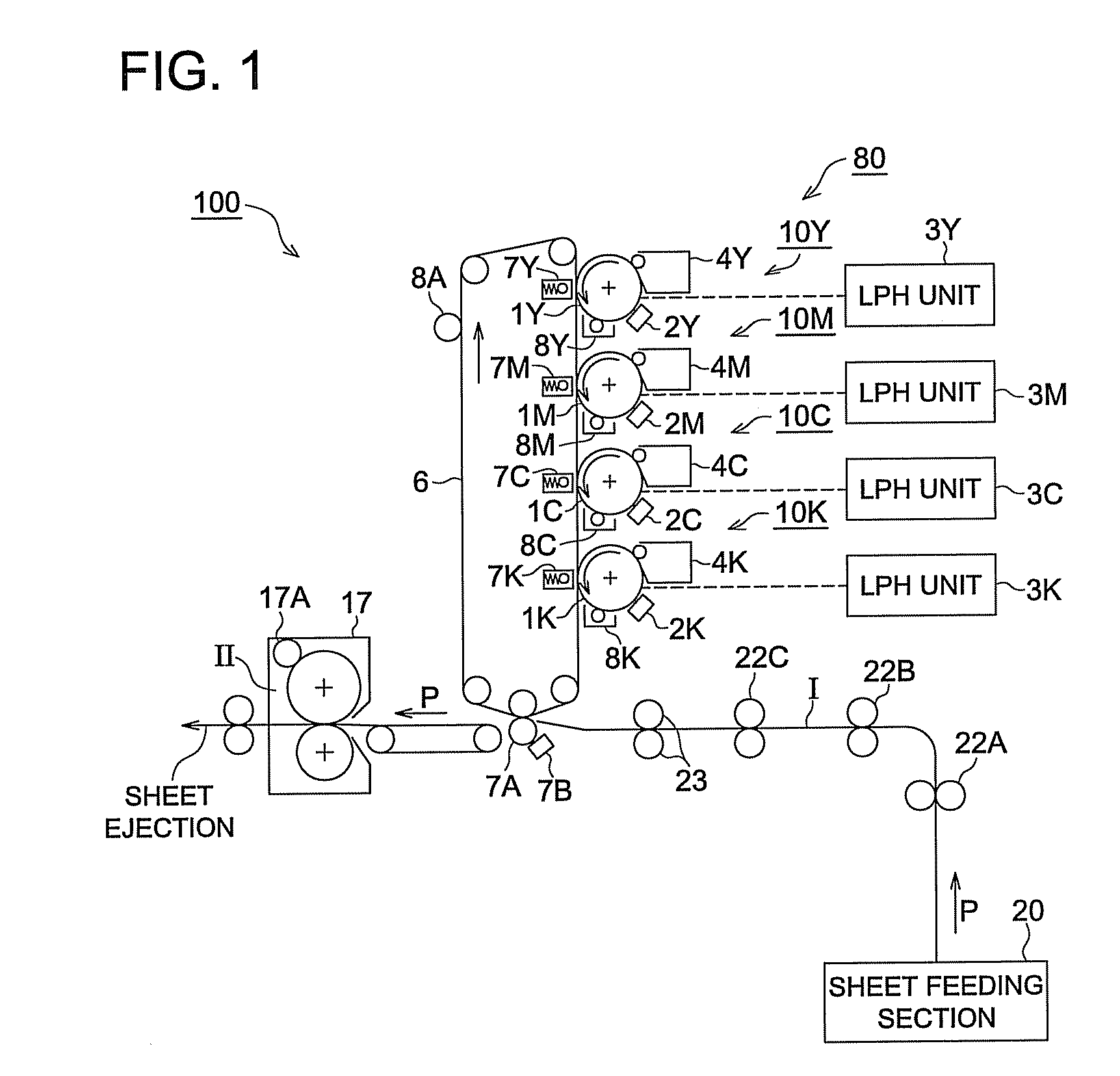
[0160]FIG. 11 is a flow chart showing a sheet interval pattern control example relating to the first embodiment. This embodiment is executed on the assumption that the correction judgment mode is executed in the ordinary operation mode and on the base of the judgment results by the correction judgment mode, the execution time of the color misalignment correction mode is decided. In this example, the case that the color misalignment amounts calculated from the detection results of the pre-marks CP formed at sheet intervals are processed statistically, thus the results are assumed as a control amount for color misalignment correction is illustrated.

[0161]Under the control conditions thereof, at Step ST1 of the flow chart shown in FIG. 11, the CPU 57 judges whether the pre-correction condition is realized or not. Here, the pre-correction condition is referred to as a condition for executing the correction judgment mode and deciding the execution time of the color misalignment correctio...

embodiment 2

[0174]FIG. 12 is a graph showing a relation example between the color misalignment amount and the monitoring time period relating to the color printer 100 of the second embodiment.

[0175]In this example, the detection results of the pre-mark CP are processed statistically, and the trend of the color misalignment amount of the pre-mark CP is predicted, and the color misalignment correction amount before the incoming of the execution time of the color misalignment correction mode is calculated. For example, two kinds of pre-marks CP such as an dedicated pattern for main scanning and an dedicated pattern for sub scanning are formed in the image boundary area IIa (at sheet intervals), and from the color misalignment amount (measured value) obtained by mark detection, weights a, b, and c are added to the appearance prediction formula (multiple regression formula) of each pre-mark CP, and a sub scanning misalignment amount Vx, a main scanning misalignment amount Hx, and a skew misalignment...

embodiment 3

[0199]FIG. 14 is a block diagram showing a constitution example of the image transfer system I and image forming system II of the color printer 200 of the third embodiment.

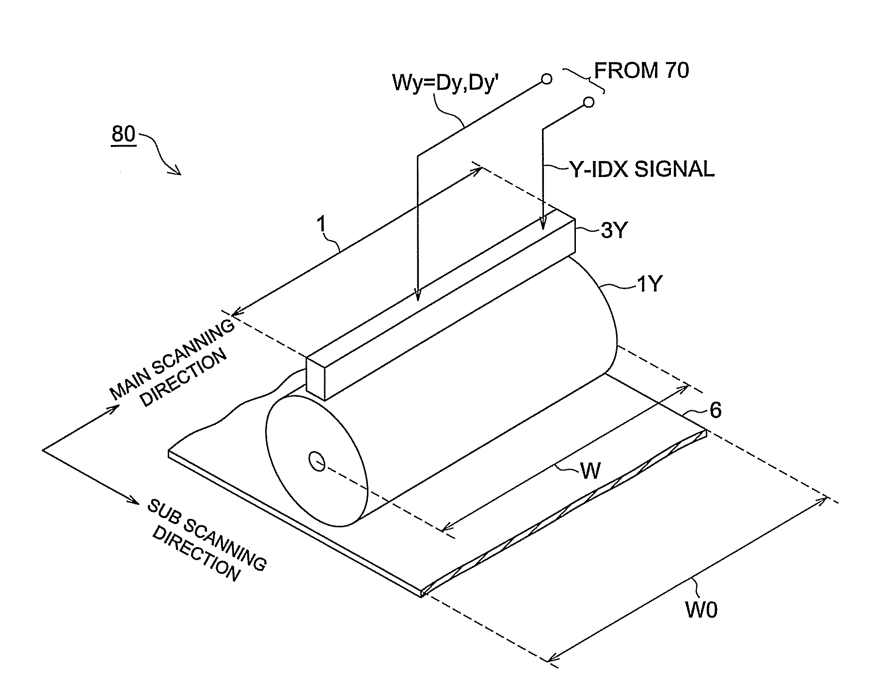
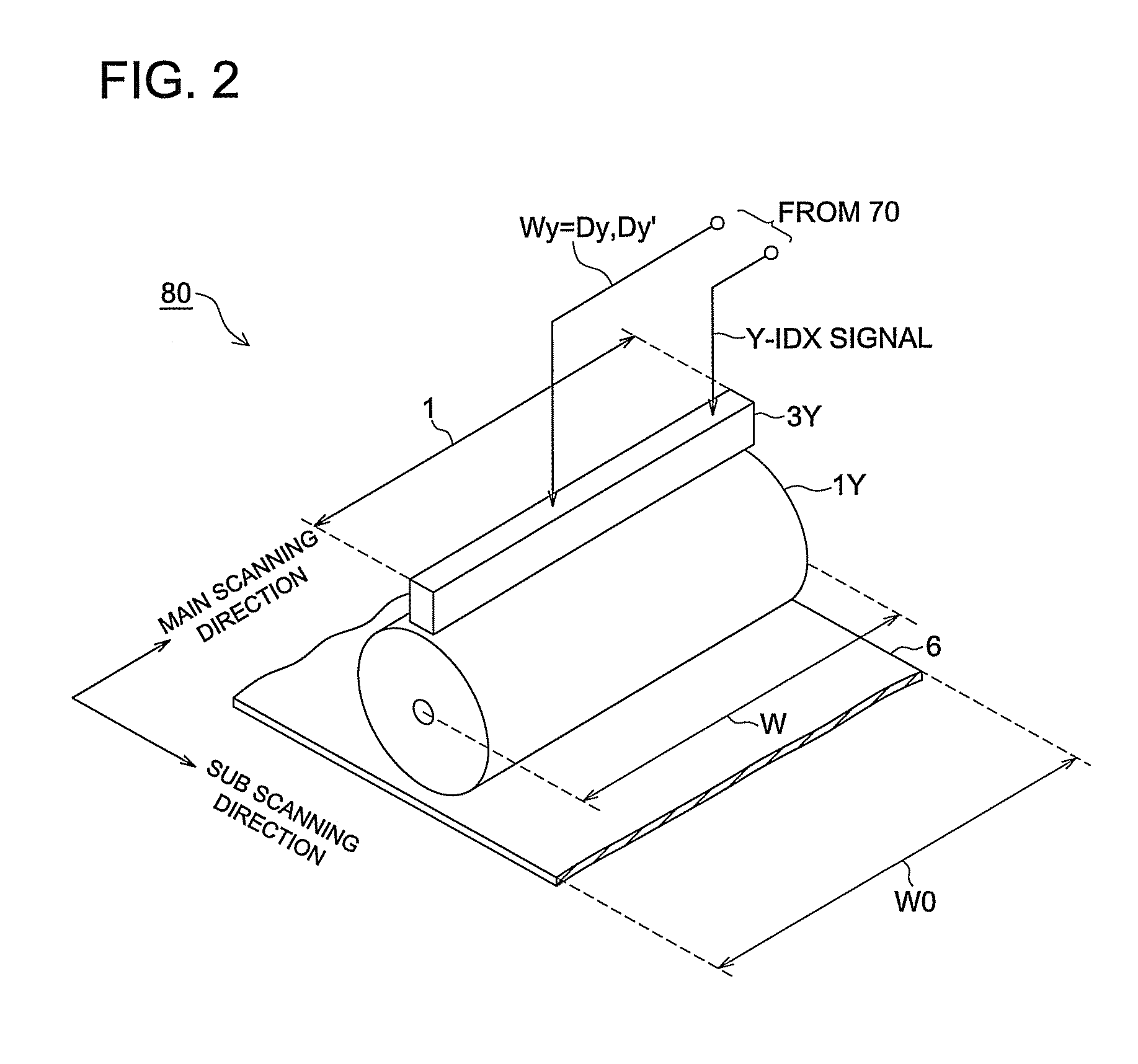
[0200]The color printer 200 shown in FIG. 14, instead of the LPH unit of the first embodiment, has laser writing units 3Y′, 3K′, 3C′, and 3K′ of a polygon mirror scanning form in the image forming section 80′, has a light source for deflection-scanning a light beam in the main scanning direction of the intermediate transfer belt 6, and exposes image information for each pixel onto the intermediate transfer belt 6.

[0201]FIG. 14 is a block diagram showing a constitution example of the image transfer system I and image forming system II of the color printer 200. The color printer 200 shown in FIG. 14 comprises the image transfer system I composed of the processing system including the intermediate transfer belt 6, sheet width sensor 11, and registration sensors 12A and 12B and the image forming system II composed of ...


PUM


Abstract

A color image forming apparatus including: an image forming section which forms an image based on image information on an image carrier provided in the image forming section; a detection section which detects a print mark for color misalignment correction formed on the image carrier by the image forming section, and outputs print mark detection information; and a control section for executing color misalignment correction control based on the print mark detection information outputted from the detection section, wherein, the control section obtains a trend of a color misalignment amount of the print mark by statistically processing data of the result of the print mark detection, calculates an execution timing of color misalignment correction base on the obtained trend, and executes the color misalignment correction at the calculated execution timing.

Description

CROSS REFERENCE TO RELATED APPLICATION[0001]The present application is based on Japanese Patent Application No. 2007-011719 filed with Japanese Patent Office on Jan. 22, 2007, the entire content of which is hereby incorporated by reference.BACKGROUND OF THE INVENTION[0002]1. Technical Field[0003]The present invention relates to a color image forming apparatus, an image forming method, and a recording medium suitably applicable to a tandem system color printer and a color copying machine having photosensitive drums and an intermediate transfer belt for executing a color misalignment correction mode and a color MFP (Multi Function Peripheral) thereof.[0004]2. Description of Prior Art[0005]In recent years, a tandem system color printer and color copying machine and a color MFP thereof have been used often. This kind of color image forming apparatus, to maintain optimally the print quality (color reproducibility) of a color image, superimposes yellow (Y), magenta (M), cyan (C), and blac...

Claims


Application Information

Patent Timeline
IPC IPC(8): H04N1/04
CPCG03G15/01G03G2215/0161G03G2215/0119
Inventor UEDA, TADAYUKIOKUTOMI, RYUJIWATANABE, HIROYUKIISOBE, AKIFUMISASAMOTO, YOSHIHITONARA, TAKASHI
Owner KONICA MINOLTA BUSINESS TECH INC
Why Eureka
Eureka Blog
Learn More