Magnetic memory cell and magnetic memory device

a magnetic memory and memory cell technology, applied in static storage, digital storage, instruments, etc., can solve the problems of increasing line current and power consumption, narrowing the effective reversal magnetic field conditions, and reducing the size of the memory cell, so as to achieve a large current density, suppress heat fluctuations of the magnetization free terminal due to joule heat, and carry out stably

Inactive Publication Date: 2008-07-24
HITACHI LTD +1
View PDF1 Cites 4 Cited by
  • Summary
  • Abstract
  • Description
  • Claims
  • Application Information

AI Technical Summary

Benefits of technology

[0012]In the above configuration, reading from the magnetic memory cell, in other words, reading of the magnetization direction of the magnetization free terminal can be performed through a current path different from that in writing into the memory cell, in other words, at the time of magnetization reversal. Since only a current having a direct current density of not more than 104 A / cm2 flows through the magnetization free terminal, heat fluctuations of the magnetization free terminal due to Joule heat can be suppressed. Moreover, for the reason described above, a relatively large current density can be used to perform writing; and this allows a writing operation to be carried out stably.
[0013]According to the present invention, it is possible to realize a magnetic memory cell which enables stable writing with a low current density required for reading and low magnetic fluctuations of the memory cell.

Problems solved by technology

As to the MRAM having the above structure, there have been pointed out, due to the structure, a drawback such as a complex process technology as well as the following three drawbacks that make the MRAM unfit for having higher density and larger capacity.
The first drawback is that effective reversal magnetic field conditions are narrowed by reduction in size of the memory cell.
The second is that a reversal magnetic field is increased by reduction in thickness of the magnetic material, and therefore a line current and power consumption are increased.
However, the magnetization reversal by use of the spin torque currently has the following technical problem.
The problem is specifically that a critical current density as high as approximately 108 A / cm2 is required to generate the spin torque that causes the magnetization reversal.
Since the TMR element utilizes a high resistance of a tunnel barrier, such a high critical current density required for magnetization reversal leads to a concern over electrostatic breakdown of the tunnel barrier.
However, since this three-terminal device structure includes three magnetic layers on a read current path, there arises a concern over a magnetic noise effect as the device is miniaturized.

Method used


Image

  • Magnetic memory cell and magnetic memory device
  • Magnetic memory cell and magnetic memory device
  • Magnetic memory cell and magnetic memory device

Examples


Embodiment Construction

[0022]With reference to the drawings, an embodiment of the present invention will be described below.

Application 1 to Solid State Memory Cell

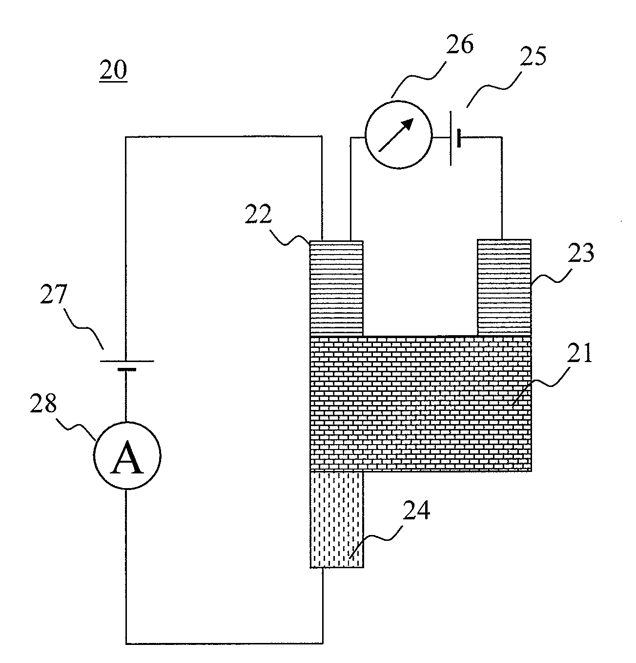
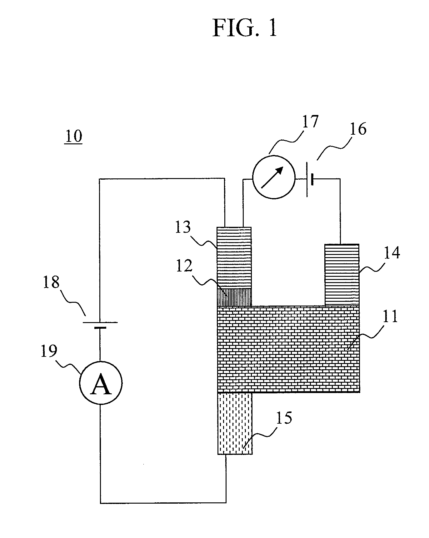
[0023]FIG. 1 is a view showing a planar structure of a magnetic memory cell 10 according to the present invention. An aluminum (Al) island (non-magnetic region) 11 having a width of 400 nm and a length of 400 nm is prepared by use of a standard electron-beam lithography technology, and a portion 12 of the Al island 11 is oxidized by use of a lift-off technique. Thereafter, a first magnetization pinned terminal 13 made of a Co thin wire having a width of 50 nm is connected to the oxidized portion 12 of the Al island so as to form a tunnel junction. Meanwhile, a second magnetization pinned terminal 14 made of a Co thin wire having a width of 100 nm and a magnetization free terminal 15 made of a permalloy (Py) thin wire having a width of 50 nm are connected to the Al island 11. In this case, the Al island 11, the magnetization pinned terminals 13 ...


PUM


Abstract

The present invention aims to reduce heat fluctuations of a memory cell and thereby provide a stable writing operation when a magnetization reversal process not involving a reversal magnetic field is used for writing into the memory cell. The magnetic memory cell has a structure where first and second magnetization pinned terminals are connected, with a space therebetween, to one surface of a non-magnetic region, and a magnetization free terminal is connected to the other surface. Magnetization directions of the first and second magnetization pinned terminals are anti-parallel to each other. Writing is performed by controlling a polarity of a current flowing between the first and second magnetization pinned terminals through the non-magnetic region and thus reversing magnetization of the magnetization free terminal. Reading is performed by detecting a magnetic resistance attributable to a change in relative magnetization direction between the first magnetization pinned terminal and the magnetization free terminal.

Description

CLAIM OF PRIORITY[0001]The present application claims priority from Japanese application JP 2007-002577 filed on Jan. 10, 2007, the content of which is hereby incorporated by reference into this application.BACKGROUND OF THE INVENTION[0002]1. Field of the Invention[0003]The present invention relates to a magnetic memory cell in which information writing and information reading are performed by the use of a magnetoresistance effect and also relates to a device using the same.[0004]2. Description of the Related Art[0005]The magnetoresistance effect is a phenomenon that an electric resistance is changed when a magnetic field is applied to a magnetic material or when a magnetization state of a magnetic material is changed. A magnetic head and a magnetic sensor have been known as a magnetoresistance effect device utilizing the magnetoresistance effect. Moreover, recently, a nonvolatile solid-state magnetic memory device (MRAM) and the like are being experimentally manufactured.[0006]A ma...

Claims


Application Information

Patent Timeline
Patent Type & Authority Applications(United States)
IPC IPC(8): G11C11/00
CPCG11C11/16
Inventor MAEKAWA, SADAMICHITAKAHASHI, SABUROIMAMURA, HIROSHIICHIMURA, MASAHIKOTAKAHASHI, HIROMASA
Owner HITACHI LTD
Why Eureka
Try Eureka