
Composite load bearing structure

a load bearing structure and composite technology, applied in the direction of rail fasteners, coatings, ways, etc., can solve the problems of insufficient supply of products, use of long time, and inability to provide adequate products, etc., to achieve equivalent loading, easy replication, and strength and stiffness

Inactive Publication Date: 2008-07-31
INTEGRICO COMPOSITES LLC
View PDF12 Cites 27 Cited by
  • Summary
  • Abstract
  • Description
  • Claims
  • Application Information

AI Technical Summary

Benefits of technology

[0017]In view of the foregoing, it is an object of the present invention to provide a composite load bearing member that is less expensive than traditional composite members.
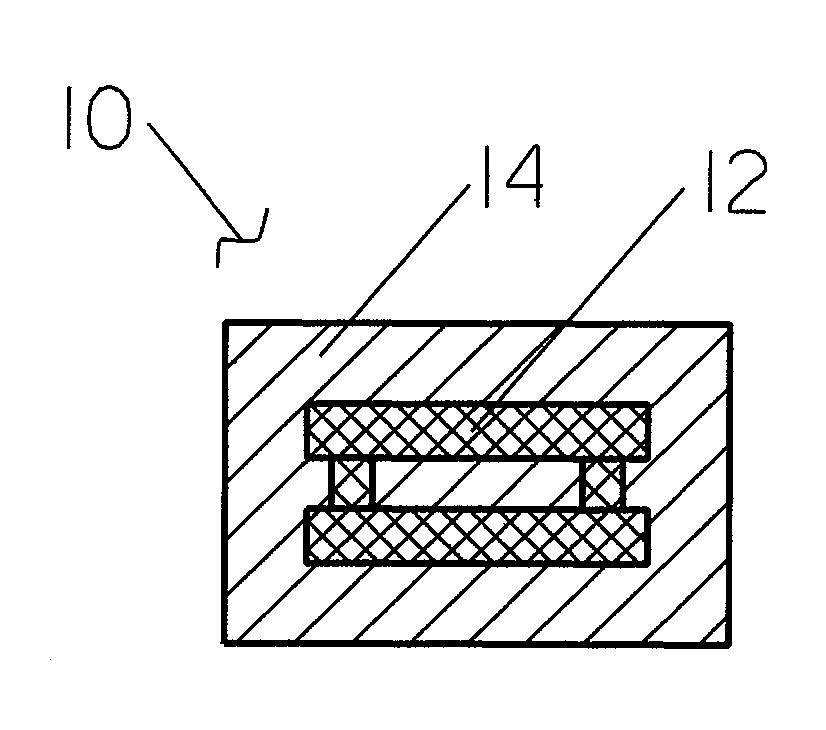
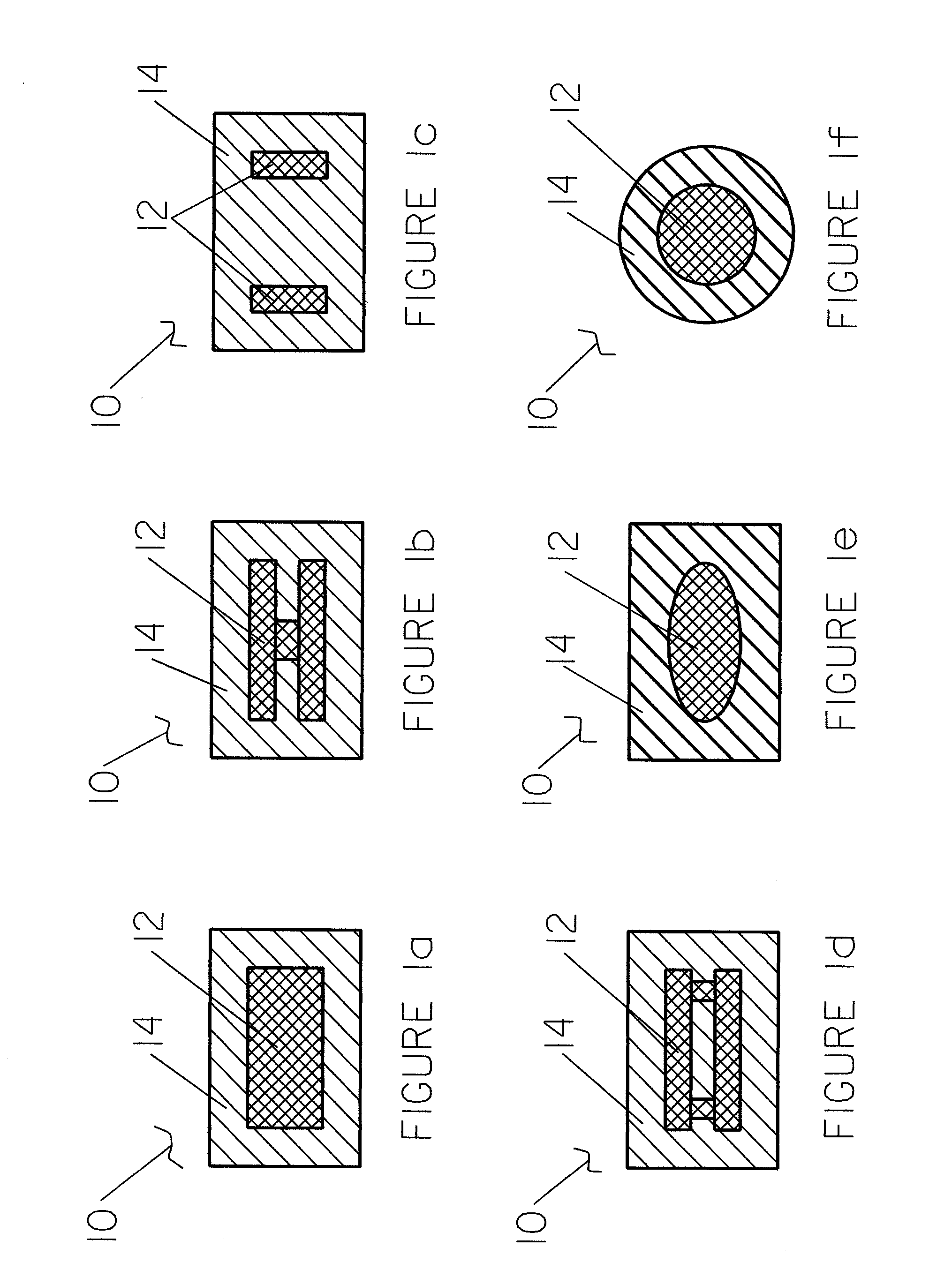
[0030]Finally, embodiments of the present invention provide significant improvements over the prior art composite load bearing members, such as composite railroad ties, marine timbers, or the like. In contrast to any of the prior art composite structural members, the present invention provides an inner member that not only provides structural integrity and stiffness to the structure, but also displaces a significant amount of polymeric material. This has the dual effect of balancing the aforementioned competing challenges of product performance and economic efficiency by taking advantage of the attributes of both the inexpensive wooden core and the durable polymeric composite providing protection. Thus, embodiments of the present invention provide a structural load bearing member, such as a railroad tie, marine timber or the like, having the performance advantages of solid wood combined with the durability advantages of prior art composite structures, with significantly less expense than that associated with prior art composite structures.

Problems solved by technology

The selection and use of materials and configurations in load bearing structures has become increasingly challenging in recent times due in part to advances in technology and the continuous development of new and better materials.
Despite these more recent demands, traditional structural members are still predominant in many current industrial sectors for various reasons, including the fact that the current state of the art has not been able to provide a product that adequately meets these existing demands.
However, the use of conventional wood railroad ties have a number of disadvantages associated therewith as well.
First and foremost, despite their predictability, wood ties must be replaced every few years making such use somewhat expensive over a long period of time.
However, the typical preservatives currently used to treat wood ties are either prone to leaching and dissipating from the wood into the surrounding environment and / or are hazardous in nature.
For instance, borate products are known for their ability to preserve wood when used as a fungicide and pesticide; however, it is also well known that the borate treatments tend to leach out of treated wood very quickly, particularly along crevices or checks in the surface of the wood itself.
In addition, creosote is currently used as a surface treatment to wood railroad ties and utility poles to preserve the wood and prevent deterioration due to insects; however, creosote is a known carcinogen, harmful to humans and animals.
In fact, the Environmental Protection Agency considered banning creosote in 1987, but the agency allowed its continued use because of the lack of suitable alternatives.
Additionally, a number of lawsuits have been filed in recent years relating to the detrimental effects of creosote usage.
Therefore, it is clearly undesirable not only to manufacture such railroad ties, but also to have such railroad ties in use and finally, to dispose of such ties as well.
In an effort to provide a railroad tie with increased longevity, railroad ties of varying material composition have developed over the years; however, none of them have had great success in replacing wood ties because of the various drawbacks associated with their respective use.
Steel ties, for instance, have realized only limited use due to a number of factors.
First, although steel is a strong, stiff material (with similar properties to wood), steel's susceptibility to rusting makes it an unattractive alternative.
Additionally, the use of steel ties is also associated with a high noise level during use.
Finally, the use of steel ties also does not facilitate the typical system of attaching rails to ties through the use of railroad tie spikes.
Therefore, steel railroad ties have emerged as an unattractive option to traditional wood ties.
Concrete ties are significantly more expensive than wood ties.
That is, since concrete is significantly heavier than wood, such ties are not able to be handled, transported, or installed using existing processes and equipment.
Furthermore, the use of concrete ties requires much more complex rail fastening systems, again increasing the cost of installation.
The use of such reinforcement potentially short-circuiting the aforementioned train locating system as well.
Because of this difference, when concrete ties are mixed into sections with existing wood ties, uneven loading occurs, resulting in significantly shorter lifespan of the surrounding wood ties.
For this reason, entire sections of railroad ties must be replaced when replacing with concrete ties, again resulting in much higher installation costs.
Thus, concrete ties are also considered an unattractive alternative to wood railroad ties.
Two competing challenges exist in the development and production of composite railroad ties: product performance and economics.
That is, virgin resin material could be used to provide the desired performance characteristics; however, the final product would be many times the cost of a wood tie.
In contrast, pure recycled polymers could be used to reduce the cost of the tie, but the material properties of such a railroad tie would not be acceptable.
However, although the desired properties with such a composition may be obtained, it is difficult to maintain such requirements throughout extensive production runs.
Moreover, manufacturing such composite ties consumes tremendous volumes of recycled plastic requiring the maintenance of multiple sources.
However, even slight variation in the quality of the recycled plastics not only has an impact on the properties of the polymer, but it also impacts the interaction between the polymers and the mineral additives.
All of this leading to railroad ties that may last five times longer than wood railroad ties but that are still unacceptable because of they lack the consistent strength and stiffness properties of wood ties.
First, the method of producing the composite tie in Neidermair is a complicated and potentially expensive one, involving the removal of all treated surfaces from an existing wood railroad tie, machining the ends to fit the end caps, and feeding the complete assembly through an extrusion process.
Additionally, the plastic coating applied to Neidermair is relatively thin and potentially easily penetrated through typical use and environmental conditions allowing a path for moisture or insects to the untreated wood inside.
Finally, the use of a traditional railroad spike is either precluded, or if used, provides an additional path for moisture or insects to the untreated wood tie inside.
However, the Richards patents also have a number of drawbacks associated therewith, particularly when used as a railroad tie.
First, the fact that the member is composed mainly of aggregate material leads to both weight and performance characteristics more similar to those associated with existing concrete ties as opposed to existing wood ties.
That is, the weight of such a tie precludes traditional transportation and installation methods as used on wood ties, and the increased density of such a tie precludes its use alongside existing wood ties because it would lead an uneven loading condition, as previously described.
Finally, existing rail connecting methods could not be used with such a tie either; rather, a more complex system of inserts and / or bolting methods must be used, as described in the Richards patents.
Similarly to traditional railroad ties, wooden marine timbers suffer from a number of drawbacks, in particular the frequent need for replacement due to the wear and tear of harsh environmental conditions.
Attempts have been made in the industry to produce longer lasting composite marine timbers through the use of recycled plastics reinforced by fiberglass rebar; however, although these timbers may provide longer life than traditional chemically treated wooden timber, they are significantly more expensive to produce and further dependent on a consistent flow of high quality virgin or recycled polymers.
Hence the long-term, economic feasibility of such members is far from sound.

Method used


Image

  • Composite load bearing structure
  • Composite load bearing structure
  • Composite load bearing structure

Examples


first embodiment

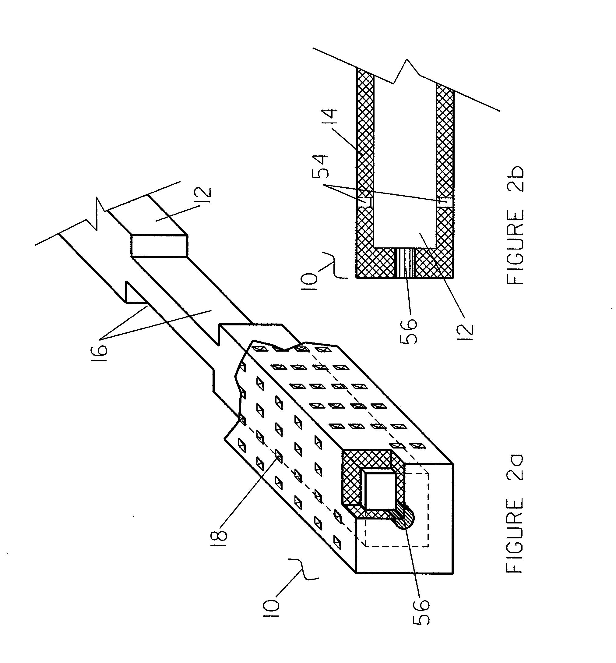
[0048]Now referring to FIG. 3, a novel apparatus and process for manufacturing the above described load bearing structure is depicted and generally referred to by the numeral 50. Mold member (52) is depicted with a cut-away section allowing a partial perspective view of inner member (12). Mold member (52) is shown in the general dimensions of a rectangular structural member, such as that of a traditional railroad tie; however, a number of variations and shapes may be accomplished and are contemplated by the present invention, including, but not limited to a cylindrical member such as that of a marine timber or fence post. Additionally, an embodiment of inner member (12) is depicted suspended in mold member (52) by a plurality of suspension members (54). A variety of suspension members (54) are contemplated by the present invention; however, three embodiments are seen to be most beneficial. suspension member (54) is in the form of any of a number of shapes, such as an angle or “T” me...

second embodiment

[0050]Furthermore, alternative embodiments of block member (56) exist as well and are contemplated by the current invention. That is, block member (56) may be a significantly thinner member than previously described and made of any of a number of materials, including metallic or composite materials. This embodiment may be used in conjunction with suspension members (54) of the second or third type as previously described, wherein suspension members (54) are configured to engage with block member (56), which resists the forces generated during the process of injecting composite (14), and provides for the prevention of suspension members (54) from embedding into inner member (12). Suspension members (54) may then either be retracted (if of the second embodiment type previously described) while composite (14) is cooling to allow composite (14) to fill in the voids left by suspension members (54). Alternatively, suspension member (54) may be removed after cooling of member (10), wherein...


PUM

PropertyMeasurementUnit
Fractionaaaaaaaaaa
Fractionaaaaaaaaaa
Fractionaaaaaaaaaa

Abstract

A composite load bearing member is provided comprising an elongated inner structural member and a thick polymeric composite outer member. An apparatus for producing the composite load bearing member is provided including devices for suspending the inner structural member within a mold cavity prior to and during injection of the polymeric composite outer member. A method of using the apparatus to produce the composite load bearing member is provided.

Description

BACKGROUND OF THE INVENTION[0001]1. Field of the Invention[0002]The present invention is generally directed toward composite load bearing structures and an apparatus and process for manufacturing composite load bearing structures. In particular, the present invention is directed toward a composite load bearing structure having an inner strengthening member. Most specifically, the present invention is directed toward a durable, long-lasting, economic alternative to traditional load bearing structures.[0003]2. Background Information[0004]The selection and use of materials and configurations in load bearing structures has become increasingly challenging in recent times due in part to advances in technology and the continuous development of new and better materials. Correspondingly, considerations and expectations involved in such a selection has grown as well, including such traditional considerations as strength and stiffness, but also including demands for more durable, long-lasting,...

Claims


Application Information

Patent Timeline
IPC IPC(8): E01B31/24
CPCE01B3/46B29C45/14073E01B3/10B29C45/14778B29C45/14819B29C45/14549
Inventor BROUGH, CHRISNIELSON, RYANYANIV, GERSHON
Owner INTEGRICO COMPOSITES LLC
Learn More