Motor and its bearing supporting structure

a technology of bearing support and motor, which is applied in the direction of bearing unit rigid support, mechanical energy handling, mechanical apparatus, etc., can solve the problems of shaft s not being able to rotate smoothly or even being jammed, the bearing support structure does not have a buffer design, and the inner hole of the shaft may deform or shrink, so as to improve the overall reliability and efficiency, enhance the product reliability and efficiency, and eliminate the limitation of the shape of the structure

Inactive Publication Date: 2008-07-31
DELTA ELECTRONICS INC
View PDF7 Cites 6 Cited by
  • Summary
  • Abstract
  • Description
  • Claims
  • Application Information

AI Technical Summary

Benefits of technology

[0014]As mentioned above, the bearing supporting structure according to the present invention has the circumferential limiting assembly between the bearing and the bushing so that the circumferential rotation of the bearing relative to the bushing can be avoided. Compared with the related art, the present invention does not need the adhesive so that the problem of the adhesive intensity can be avoided and it is possible to prevent the adhesive from entering the inner hole of the bearing. In addition, the present invention does not need the interference fit so that it is possible to prevent the inner hole of the bearing from being forced to deform or shrink and to prevent the shaft from being jammed. Thus, the product reliability and the efficiency can be enhanced.
[0015]In addition, the present invention further has the axial limiting assembly or the limiting portion of the bushing pressing against the bearing to prevent the bearing from being moved axially so that the overall reliability and efficiency can be enhanced. Furthermore, the present invention changes the method of manufacturing the members by way of non-cutting cold working so as to eliminate the limitation to the shape of the structure, to enlarge the design allowance and to avoid the problems of the material waste and the variation during the manufacturing process.

Problems solved by technology

However, the bearing supporting structure does not have the buffer design.
Therefore, the shaft S cannot be rotated smoothly or may even be jammed.
Furthermore, the variations of the material and the manufacturing process caused by the interference fitting will make the bearing 12 be over forced so that the inner hole thereof may deform or shrink.
Thus, the bearing 12 is abnormally worn, the reliability thereof is influenced and the product lifetime is shortened, and even the shaft S may be jammed.
In addition, the use of the adhesive will cause the drawback of the insufficient adhesive intensity, or the drawback that the adhesive enters the inner hole of the bearing 12 to make the shaft S be jammed.
If the bushing 11 is formed by way of plastic molding, the molding machine has high investment cost, high mold cost, poor stability (because it tends to be deformed or softened when heated) and poor temperature reliability.
If the bushing 11 is formed by way of turning, the apparatus (CNC lathe) has high investment cost, poor throughput (about 3000 to 5000 pieces per 24 hours), large material waste (the availability is lower than 60%), higher cost and difficulty of the stability control.
If the bushing 11 is formed by way of hot pressing, the die-casting machine has high investment cost, high mold cost and poor dimensional stability.
Also, if the precise dimension has to be obtained, the secondary precise machining is needed and the machining cost is much higher.

Method used


Image

  • Motor and its bearing supporting structure
  • Motor and its bearing supporting structure
  • Motor and its bearing supporting structure

Examples


Embodiment Construction

[0024]The present invention will be apparent from the following detailed description, which proceeds with reference to the accompanying drawings, wherein the same references relate to the same elements.

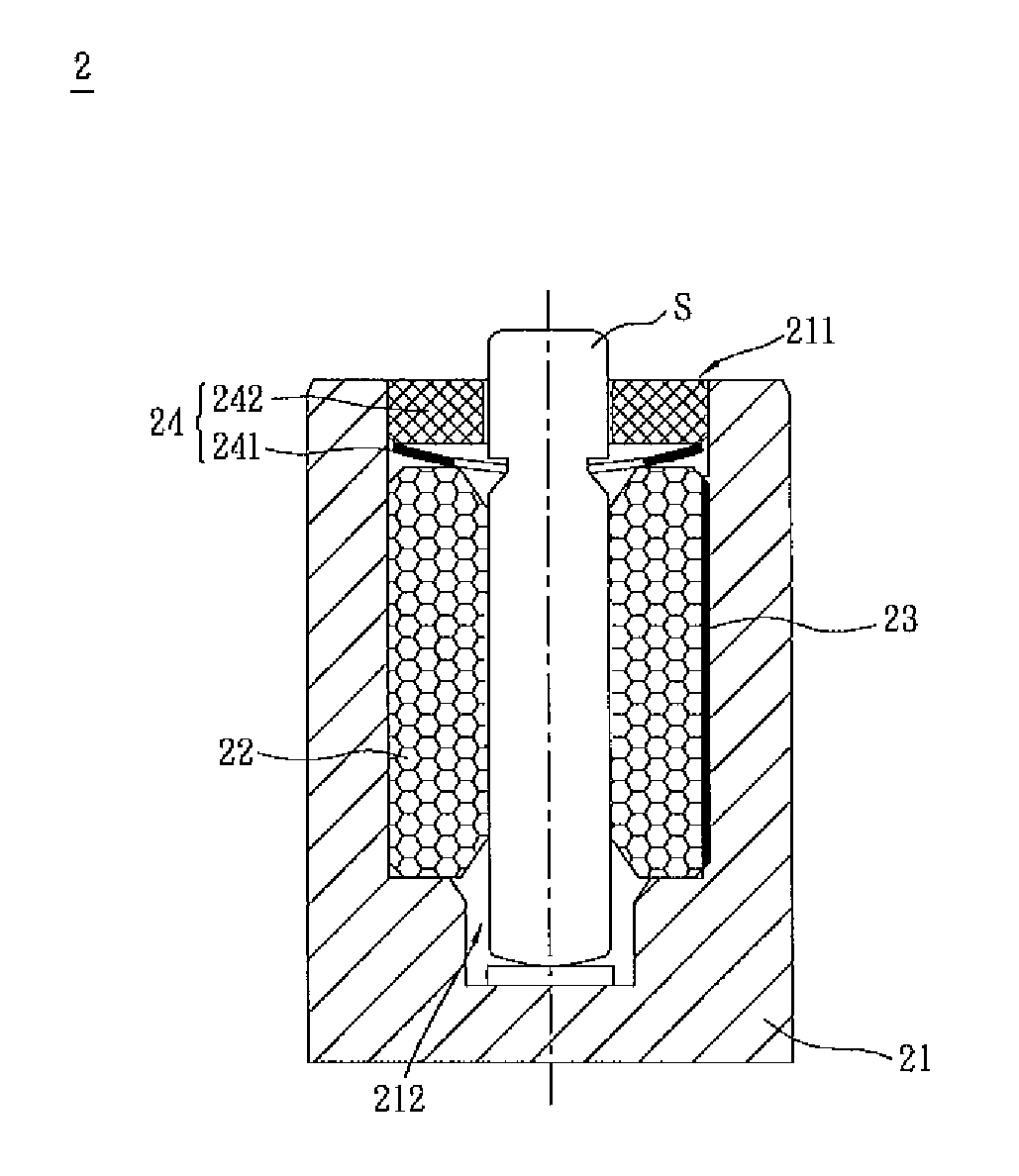
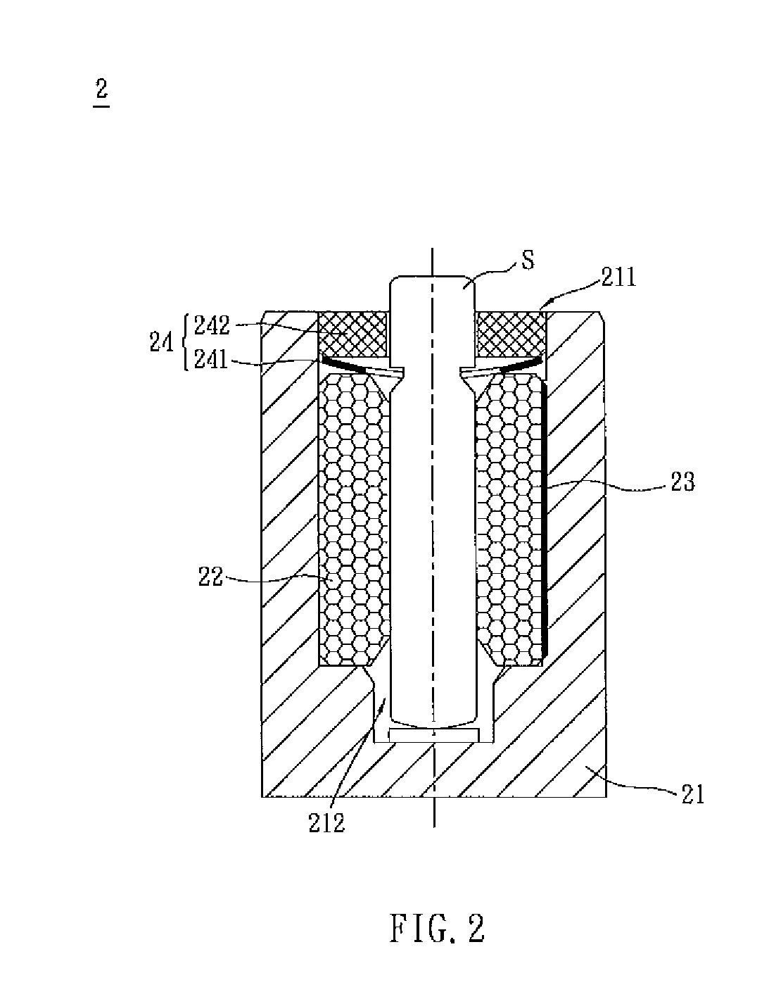
[0025]Referring to FIG. 2, a bearing supporting structure 2 according to an embodiment of the present invention is for supporting a shaft S and includes a bushing 21 and a bearing 22. The bushing 21 has an opening 211 and an accommodating space 212. The bearing 22 is disposed in the accommodating space 212 of the bushing 21. The shaft S passes through the bearing 22, and the bearing 22 is for supporting at least a portion of the shaft S. The bearing supporting structure 2 further includes at least one first limiting assembly 23, such as a circumferential limiting assembly, disposed at a connection of the bearing 22 and the bushing 21 to prevent the bearing 22 from being rotated circumferentially, for example, relative to the bushing 21. The bearing 22 may be a sleeve bearing, a ball b...


PUM


Abstract

A motor and its bearing supporting structure are disclosed. The bearing supporting structure supporting a shaft includes a bushing, a bearing and at least one first limiting assembly. The bushing has an opening and an accommodating space. The bearing supports at least a portion of the shaft and is disposed in the accommodating space. The first limiting assembly is disposed at a connection of the bearing and the bushing.

Description

CROSS REFERENCE TO RELATED APPLICATIONS[0001]This Non-provisional application claims priority under 35 U.S.C. §119(a) on Patent Application No(s). 096103002, filed in Taiwan, Republic of China on Jan. 26, 2007, the entire contents of which are hereby incorporated by reference.BACKGROUND OF THE INVENTION[0002]1. Field of Invention[0003]The present invention relates to a motor and its bearing supporting structure, and, in particular; to a bearing supporting structure for fixing a bearing to prevent it from being moved relative to a bushing, and a motor having the bearing supporting structure.[0004]2. Related Art[0005]An electronic device (e.g., a fan or a hard disk drive) has a rotatable component, which is often driven by a motor. The driving element has a bearing for supporting a shaft to rotate.[0006]Referring to FIG. 1, a conventional bearing supporting structure 1 has a bushing 11 and a bearing 12. The bushing 11 has an opening 111, and the bearing 12 is disposed in the bushing 1...

Claims


Application Information

Patent Timeline
Patent Type & Authority Applications(United States)
IPC IPC(8): H02K5/167F16C35/02
CPCF16C35/02H02K1/187H02K2211/03H02K11/0073H02K5/163H02K11/33
Inventor CHEN, ZHIN-CHANGZHOU, HONG-TULIU, JIAN-BIN
Owner DELTA ELECTRONICS INC
Why Eureka
Try Eureka