

Microfluidic valve filler and valve unit including the same
a technology of microfluidic valves and valve units, applied in laboratory glassware, magnetic bodies, other chemical processes, etc., can solve the problems of difficult miniaturization and integration of substrates for biochemical reactions, difficult to precisely control the timing of opening channels, and long melting point of paraffin wax, etc., to achieve quick melting
- Summary
- Abstract
- Description
- Claims
- Application Information
AI Technical Summary
Benefits of technology
Problems solved by technology
Method used
Image

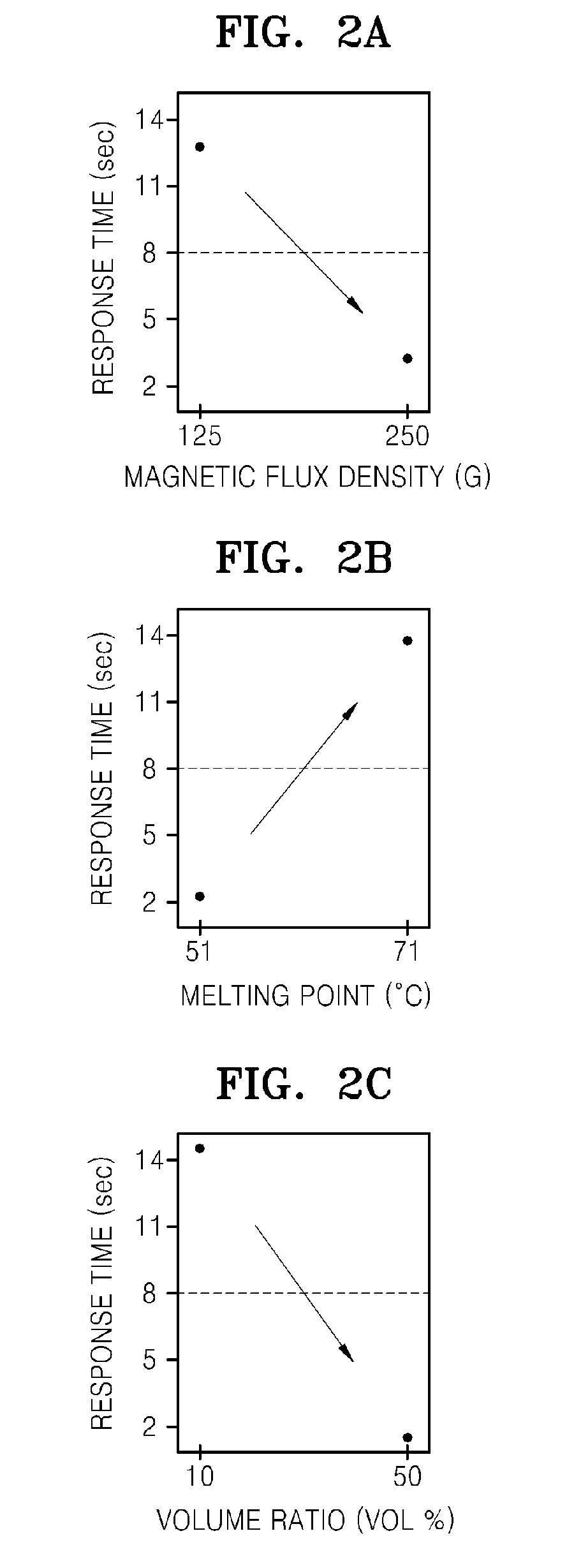
Examples
Embodiment Construction
[0033]The present invention will now be described more fully with reference to the accompanying drawings, in which exemplary embodiments of the invention are shown.
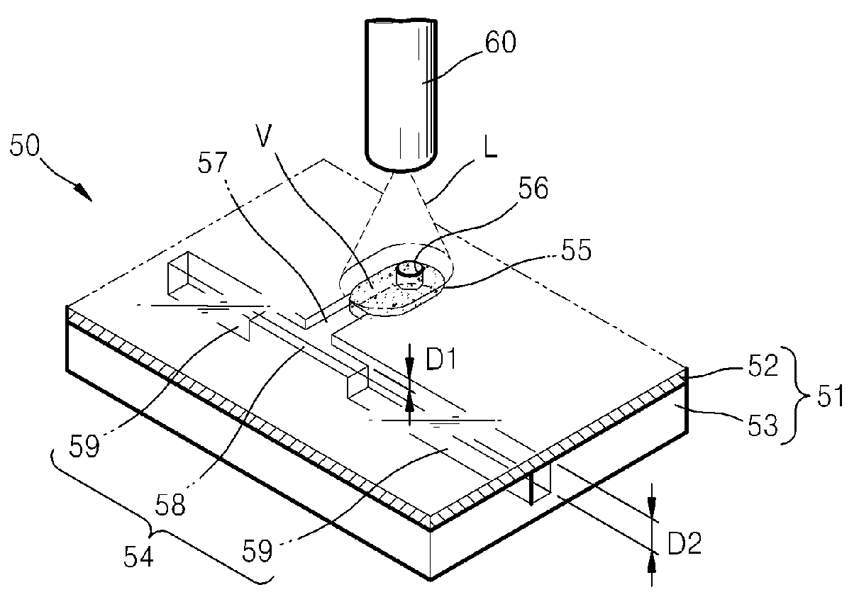
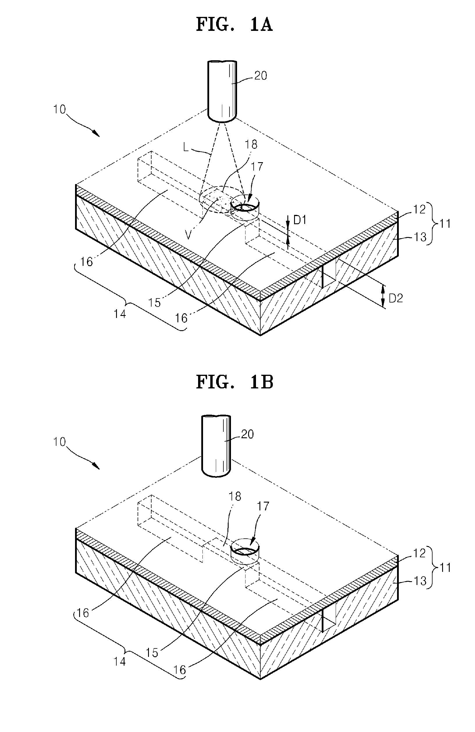
[0034]FIG. 1A is a perspective view of a valve unit 10 according to an embodiment of the present invention when a channel 14 is closed. FIG. 1B is a perspective view of the valve unit 10 of FIG. 1A when the channel 14 is opened.
[0035]Referring to FIG. 1A, the valve unit 10 includes the channel 14 forming the flow path of a fluid, a valve filler V closing the channel 14, and a laser light source 20, which is an external energy source, supplying energy to the valve filler V. The channel 14 is a micro-channel formed in a substrate 11. The substrate 11 includes an upper plate 12 and a lower plate 13 bonded to each other. The upper and lower plates (12, 13) may be formed of a material known in the art, which includes, but is not limited to, polycarbonate. The upper plate 12 and the lower plate 13 may be bonded to each other by...
PUM
| Property | Measurement | Unit |
|---|---|---|
| Temperature | aaaaa | aaaaa |
| Temperature | aaaaa | aaaaa |
| Time | aaaaa | aaaaa |
Abstract
Description
Claims
Application Information