Fuel Cell System

a fuel cell and system technology, applied in the direction of fuel cell control, fuel cells, electrical equipment, etc., can solve the problems of difficult detection of sealing defects, difficult to obtain fuel exhaust air, and high concentration of hydrogen gas leakage through the purge valve to the outside of the system, so as to reduce the hydrogen concentration of exhaust gas and reduce the concentration of fuel gas

Active Publication Date: 2008-08-07
NISSAN MOTOR CO LTD
View PDF5 Cites 25 Cited by
  • Summary
  • Abstract
  • Description
  • Claims
  • Application Information

AI Technical Summary

Benefits of technology

[0005]In a fuel cell system including the hydrogen gas circulation system, if there is a deficiency such as a sealing defect in a purge valve, high-concentration hydrogen gas leaks through the purge valve to the outside of the system when the air-electrode oxygen consumption operation is performed. It is difficult to detect the sealing defect, which is caused, for example, by a foreign object caught in the sealing.
[0006]Further, during the air-electrode oxygen consumption operation, it is impossible to obtain exhaust air from the fuel cell stack, and consequently, it is impossible to reduce hydrogen concentration of the exhaust gas by diluting the exhaust gas from the exhaust valve.
[0007]The present invention has been made in the light of these problems. An object of the invention is to provide a fuel cell system which can stop, without discharging high-concentration hydrogen gas to the outside of the system, power generation of a fuel cell even in a case, for example, where there is a deficiency such as a sealing defect in a purge valve in the fuel gas circulation system.
[0008]An aspect of the present invention is a fuel cell system comprising: a fuel cell to generate electric power, being supplied with a fuel gas to a fuel electrode thereof and an oxidant gas to an oxidant electrode thereof; a fuel gas supplying device which supplies the fuel gas to the fuel electrode of the fuel cell; an oxidant gas supplying device which supplies the oxidant gas to the oxidant electrode of the fuel cell; a fuel gas pressure detector which detects fuel gas pressure at the fuel electrode of the fuel cell; a fuel gas pressure regulating device which regulates fuel gas pressure at the fuel electrode of the fuel cell; an exhaust fuel gas discharging device which discharges exhaust fuel gas from the fuel electrode of the fuel cell to the outside, the exhaust fuel gas discharging device including a purge valve; an exhaust fuel gas treatment device which treats the exhaust fuel gas discharged from the purge valve to reduce fuel gas concentration thereof; and a controller which controls power generation of the fuel cell, wherein the controller: continues power generation of the fuel cell, controlling the fuel gas pressure regulating device to lower the fuel gas pressure at the fuel electrode, having the oxidant gas supplying device continuing supplying the oxidant gas to the oxidant electrode and the purge valve closed; and after the fuel gas pressure at the fuel electrode becomes equal to or lower than the atmospheric pressure, stops power generation of the fuel cell and gas treatment of the exhaust fuel gas treatment device.

Problems solved by technology

In a fuel cell system including the hydrogen gas circulation system, if there is a deficiency such as a sealing defect in a purge valve, high-concentration hydrogen gas leaks through the purge valve to the outside of the system when the air-electrode oxygen consumption operation is performed.
It is difficult to detect the sealing defect, which is caused, for example, by a foreign object caught in the sealing.
Further, during the air-electrode oxygen consumption operation, it is impossible to obtain exhaust air from the fuel cell stack, and consequently, it is impossible to reduce hydrogen concentration of the exhaust gas by diluting the exhaust gas from the exhaust valve.

Method used


Image

  • Fuel Cell System
  • Fuel Cell System
  • Fuel Cell System

Examples


first embodiment

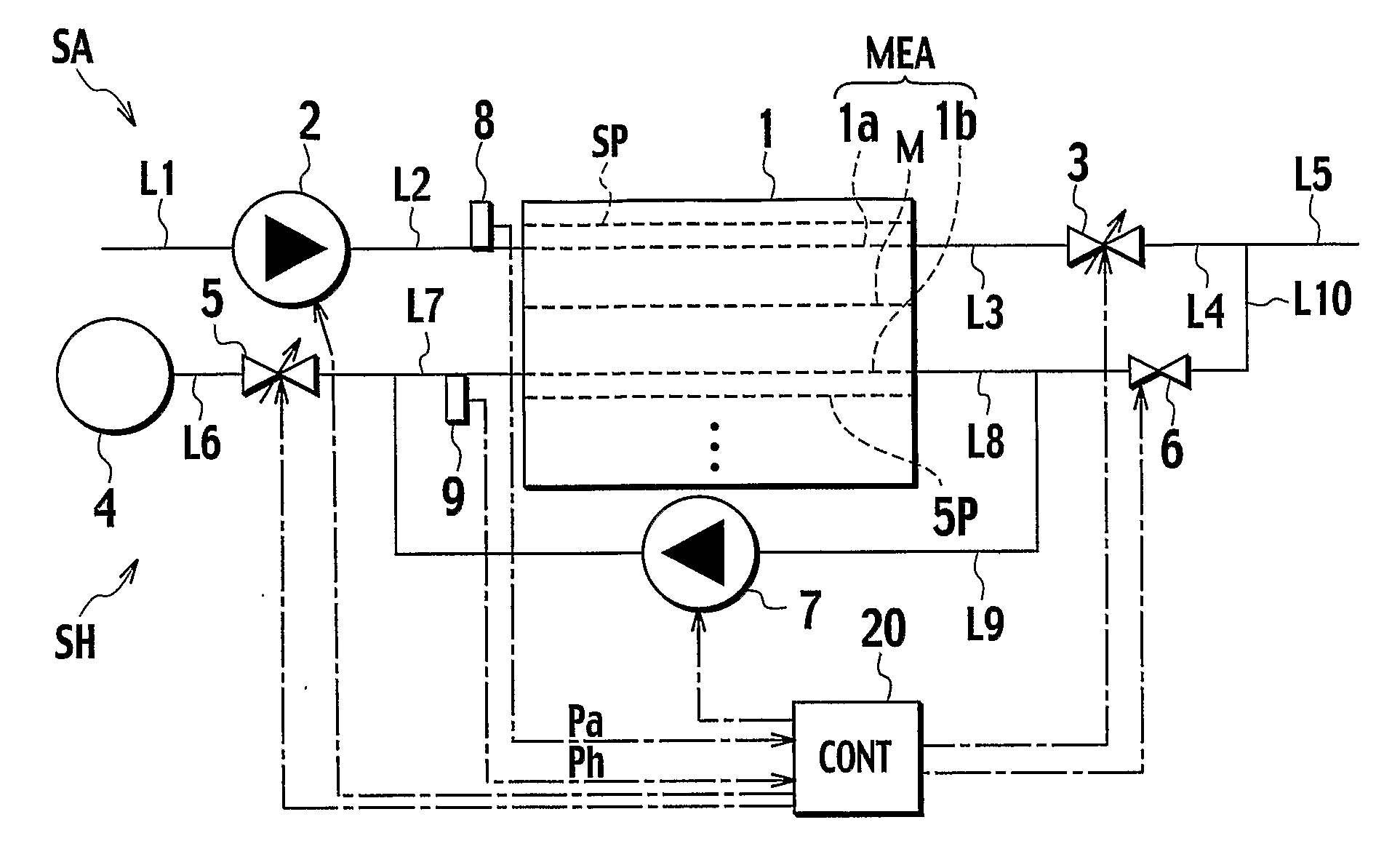
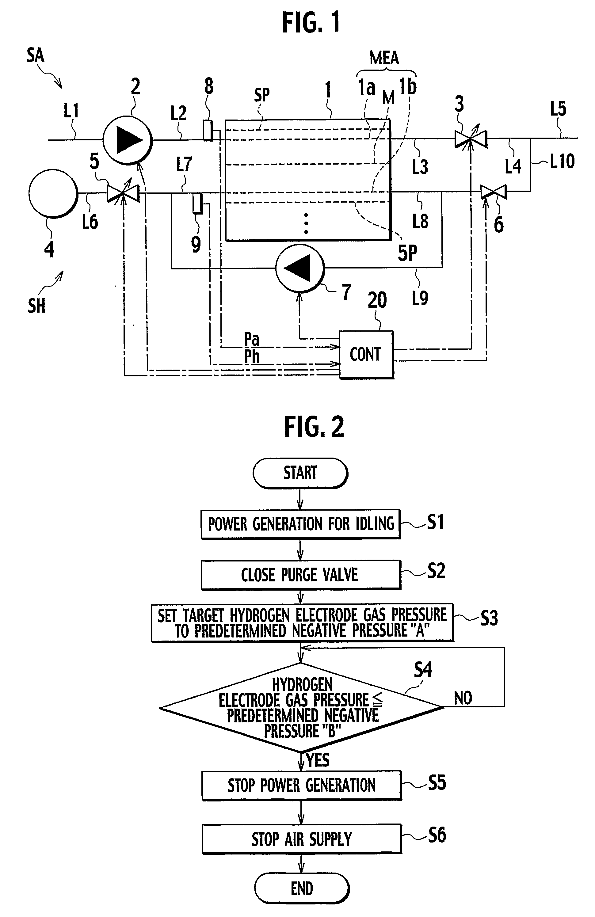
[0023]The present invention is applied to, for example, a fuel cell system configured as shown in FIG. 1.

[0024]This fuel cell system includes a fuel cell stack 1 in which a plurality of unit cells are stacked on one another. Each of the unit cells (a fuel cell) is configured with a membrane electrode assembly MEA and a pair of separators SP sandwiching the MEA. The membrane electrode assembly MEA includes an air electrode 1a (oxidant electrode), a hydrogen electrode 1b (fuel electrode), and a polymer electrolyte membrane M interposed therebetween. The fuel cell stack 1 generates electric power by an electrochemical reaction between hydrogen gas supplied as a fuel gas to the hydrogen electrodes 1b and air supplied as an oxidant gas to the air electrodes 1a.

[0025]The fuel cell system includes an air system SA and a hydrogen gas system SH. The air is introduced into and discharged from the air electrodes 1a of the fuel cell stack 1 by the air system SA. The hydrogen gas is introduced ...

second embodiment

[0042]Next, a description will be given of a fuel cell system according to a second embodiment. Note that, with respect to the same parts as those of the first embodiment, detailed descriptions are omitted, giving the same reference numerals and characters thereto.

[0043]The fuel cell system according to the second embodiment is characterized in that an operation is added of consuming oxygen of the air electrodes 1a at the time of stopping power generation of the fuel cell stack 1.

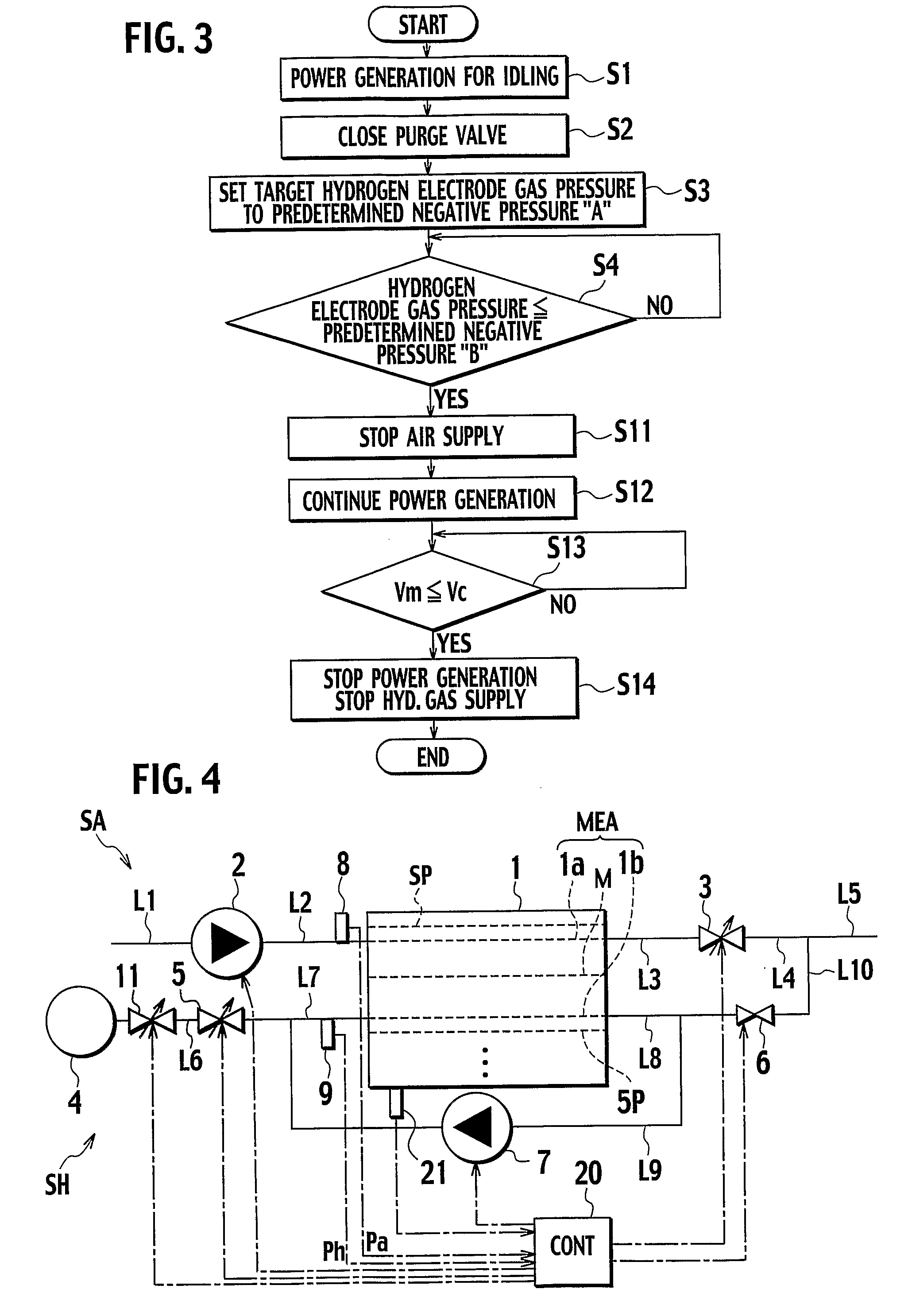
[0044]In the power generation stopping process in the second embodiment, as shown in FIG. 3, after it is judged that the gas pressure at the hydrogen electrodes 1b has become the second predetermined negative pressure B or lower in Step S4, the operation of the compressor 2 is stopped in Step S11 in order that the air supply to the fuel cell stack 1 can be stopped. Then in Step S12, the opening of the hydrogen gas pressure regulating valve 5 is adjusted so as to supply hydrogen, which is equivalent in amoun...

third embodiment

[0049]Next, a description will be given of a fuel cell system according to a third embodiment. Note that, with respect to the same parts as those of the abovementioned embodiments, detailed descriptions are omitted, giving the same reference numerals and characters thereto.

[0050]The fuel cell system according to the third embodiment, as shown in FIG. 4, is different from the fuel cell system according to the first embodiment in that a hydrogen gas supply shutoff valve 11 is provided in the supply hydrogen gas passage L6 between the hydrogen tank 4 and the hydrogen gas pressure regulating valve 5, and is controlled by the controller 20.

[0051]In the fuel cell system, in a power generation stopping process, the hydrogen gas supply shutoff valve 11 is set closed, while the hydrogen gas pressure regulating valve 5 is set closed, so as to block hydrogen gas supply to the fuel cell stack 1 from the hydrogen tank 4 in order to bring the gas pressure at the hydrogen electrodes 1b to the firs...


PUM

PropertyMeasurementUnit
pressureaaaaaaaaaa
pressureaaaaaaaaaa
electric poweraaaaaaaaaa

Abstract

A fuel cell system including: a fuel cell supplied with a fuel gas to a fuel electrode thereof and air to an air electrode thereof; a fuel gas supplying device which supplies the fuel gas to the fuel electrode; an air supplying device which supplies air to the air electrode; a fuel gas pressure regulator which regulates fuel gas pressure at the fuel electrode; a purge valve which discharges exhaust fuel gas from the fuel electrode to the outside; and a controller. The controller continues power generation of the fuel cell, controlling the fuel gas pressure regulator to lower the fuel gas pressure at the fuel electrode, having the air supplying device continuing supplying air to the air electrode with the purge valve closed; and after the fuel gas pressure at the fuel electrode becomes equal to or lower than the atmospheric pressure, stops power generation of the fuel cell.

Description

TECHNICAL FIELD[0001]The present invention relates to a fuel cell system including a fuel cell to which fuel gas and oxidant gas are supplied to generate electric power, and treating gas discharged from the fuel cell when stopping the power generation.BACKGROUND ART[0002]In a fuel cell system including a polymer electrolyte fuel cell stack to which hydrogen gas (fuel gas) and air (oxidant gas) are supplied to generate electric power, stable power generation is generally realized by supplying to the fuel cell stack an amount of hydrogen gas more than that of hydrogen gas consumed therein. Additionally, the fuel cell system includes a hydrogen gas circulation system whereby, by allowing excess hydrogen gas discharged from a fuel cell stack to be circulated into a hydrogen-gas inlet of the fuel cell stack, the excess hydrogen gas is reused and efficiency of hydrogen gas use is thus enhanced.[0003]In the hydrogen gas circulation system, due to such a cause as nitrogen permeation in the ...

Claims


Application Information

Patent Timeline
Patent Type & Authority Applications(United States)
IPC IPC(8): H01M8/04
CPCH01M8/04231Y02E60/50H01M8/04358H01M8/04388H01M8/04395H01M8/04447H01M8/04552H01M8/04559H01M8/04589H01M8/04619H01M8/04626H01M8/04753H01M8/04761H01M8/0491H01M8/04955H01M8/0662H01M2008/1095H01M8/04298
Inventor KAMIHARA, TETSUYAIIMORI, TAKASHIIGARASHI, HITOSHI
Owner NISSAN MOTOR CO LTD
Why Eureka
Try Eureka