Ion generator and neutralizer

Inactive Publication Date: 2008-08-14
NAT INST OF ADVANCED IND SCI & TECH
View PDF11 Cites 5 Cited by
  • Summary
  • Abstract
  • Description
  • Claims
  • Application Information

AI Technical Summary

Benefits of technology

[0054]According to the invention described in the above (3), use as an ionizer having sufficient ioniza

Problems solved by technology

Therefore, to generate a sufficient amount of ions by applying a DC voltage to the needle electrode, much power is consumed, and the power supply unit inevitably increases in size.
However, with this high frequency, a large amount of ozone is produced as a by-product, and due to heating, stable operation is difficult.
In a conventional needle-like ion generating electrode, influences from dust accumulation and wearing due to physical sputtering make it difficult to cause corona discharge, and the ion generation efficiency tends to be lowered.
Also, in a ground electrode which is opposed to the needle-like ion generating electrode and provided for stabilizing discharge, due to electrostatic adsorption according to a high voltage and physical sputtering of the ion generating electrode, dust accumulates and the surface is contaminated, and these deteriorate the ion generation efficiency.
Such maintenance involves cleaning of the inside of a structure having the pointed portion, and as a high voltage is applied to this portion, the maintenance is dangerous and troublesome.
An ionizer which includes a mechanism for cleaning has been also developed, however, this requires a complicated mechanism (refer to Patent Document 3).
In the case where positive ions and negative ions are generated from an ion generating element by applying a high voltage to the above-described electrode structure formed via a dielectric body, a first problem is that the ion bal

Method used


Image

  • Ion generator and neutralizer
  • Ion generator and neutralizer
  • Ion generator and neutralizer

Examples


Embodiment Construction

[0065]In the description given below, for convenience, the ion generator of the present invention is referred to as a first aspect of the invention, and an ionizer using this ion generator is referred to as a second aspect of the invention.

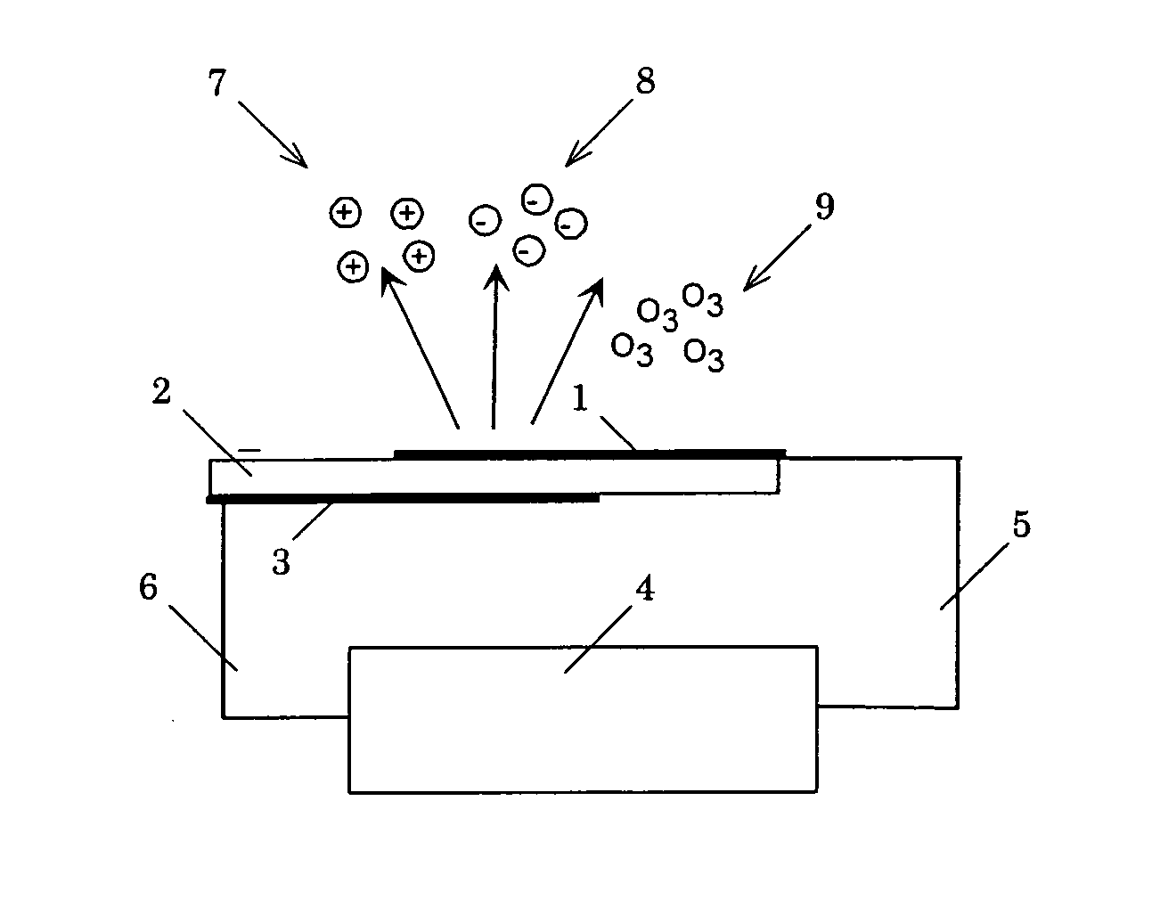
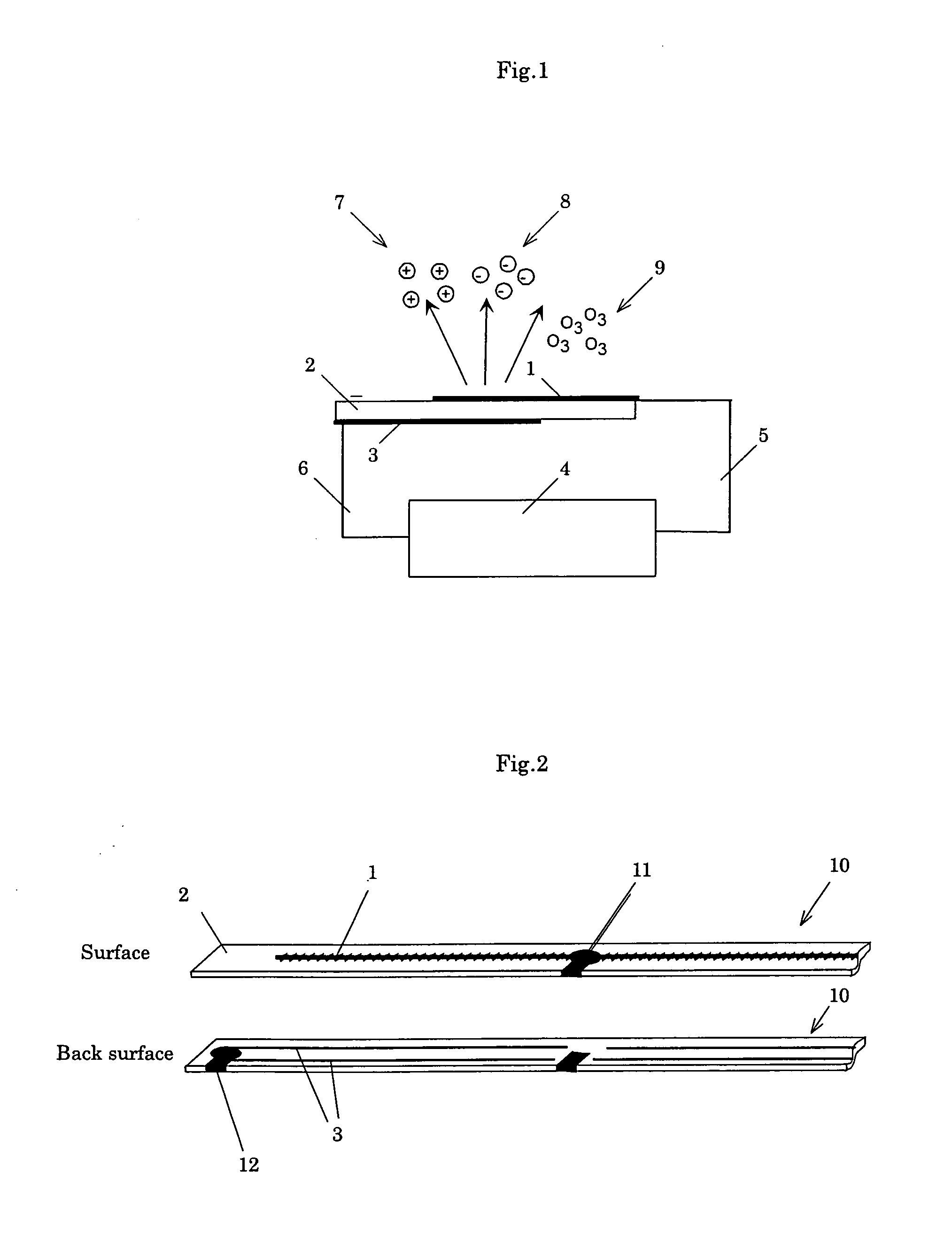
[0066]First, the first aspect of the invention will be described with reference to the accompanying drawings. FIG. 1 shows an ion generator of the present invention. The ion generator 10 of the present invention includes a discharge electrode 1, a dielectric body 2, an induction electrode 3, and a power supply 4, and by fine machining, the discharge electrode 1 is formed on the surface of the dielectric body 2, and the induction electrode 3 is formed on the back surface. A sinusoidal AC high voltage is applied to the discharge electrode 1 via voltage lead wires 5 and 6, and a potential difference from the induction electrode 3 is provided, whereby plasma is formed on the surface of the dielectric body 2, and by air ionization, positive ions 7, neg...


PUM


Abstract

The present invention is relating to an ion generator and an ionizer, in which the ion generator can obtain stable ion generation even if the electrode and the power supply slightly change, satisfies voltage and frequency conditions for realizing an ozone concentration less than 50 ppb as an allowable concentration. The ion generator of the present invention is characterized as a fan-type ion generator including a dielectric body, a discharge electrode having fine protrusions arranged on the surface of this dielectric body, and an induction electrode arranged on the back surface of the dielectric body, comprising: an ion element in which by applying a sinusoidal AC high voltage to the discharge electrode, a potential difference from the induction electrode is generated, plasma is formed on the surface of the dielectric body, and positive ions, negative ions, and ozone are produced according to air ionization; and a fan which generates an airflow with respect to the discharge electrode, wherein the peak-to-peak voltage is not less than 3.5 kV and not more than 7 kV, the frequency f, and the relationship between the voltage V and the frequency f satisfies a specific parameter. And, the ionizer of the present invention is characterized that ionization is performed by using the above mentioned fan-type ion generator.

Description

BACKGROUND OF THE INVENTION[0001]1. Field of the Invention[0002]The present invention relates to an ion generator which generates air ion clusters and an ionizer which removes static electricity on an object surface, and more specifically, to an ion generator and an ionizer having regulated design ranges of voltage, frequency, and airflow rate for efficient generation and conveyance of ions by a plate-like ion generating element.[0003]2. Description of the Background Art[0004]Among conventional general ion generators and ionizers, for example, in the case of a conventional ionizer, corona discharge is caused by applying a high voltage by a high-voltage power supply to a pointed-needle-like ion generating electrode, whereby the air is ionized (for example, refer to Patent Document 1). The needle-like ion generating electrode must form a local electric field at its tip end portion for forming plasma according to air ionization, and its voltage is 5 to 7 kV or more in the case of using...

Claims


Application Information

Patent Timeline
IPC IPC(8): H01J27/00
CPCH01T23/00A61L9/22H05F3/04
Inventor SETO, TAKAFUMIHIRASAWA, MAKOTOHOZUMI, YASUFUMITSUJI, MASAAKIOKUYAMA, AKIRASAITO, SUSUMU
Owner NAT INST OF ADVANCED IND SCI & TECH
Why Eureka
Try Eureka