
Method of producing molding die for use in producing a ceramic honeycomb structure body

a technology of ceramic honeycomb and mold, which is applied in the direction of dough shaping, manufacturing tools, applications, etc., can solve the problems of large amount of error, only having a positioning accuracy of 50 m, and not acceptable for a fine structure forming process, so as to prevent the occurrence of variations in width and step

Inactive Publication Date: 2008-08-14
DENSO CORP
View PDF4 Cites 12 Cited by
  • Summary
  • Abstract
  • Description
  • Claims
  • Application Information

AI Technical Summary

Benefits of technology

[0010]It is an object of the present invention to provide a method of producing a molding die for use in producing (such as extruding and molding) honeycomb structure bodies, where the method is capable of preventing the occurrence of variations in width and step of slit grooves formed in the molding die.

Problems solved by technology

However, the above alignment manner in the related-art method only has a positioning accuracy of ±50 μm because the position of the reference mark is determined based on the image data obtained by the camera of the slit groove formation system.
Although this positioning accuracy is acceptable for a rough forming process and the like, but it is not acceptable for a fine structure forming process such as the slit groove formation process of not more than 100 μm width.
In the slit groove formation process, a large amount of error between the formation position of the pillar of the high-pressure water jet corresponding to the slit groove formation position and the irradiation position of the laser light which passes through the pillar of the high-pressure water jet.
This causes various problems such as the variations in width and step of the slit grooves formed in the molding die.

Method used


Image

  • Method of producing molding die for use in producing a ceramic honeycomb structure body
  • Method of producing molding die for use in producing a ceramic honeycomb structure body
  • Method of producing molding die for use in producing a ceramic honeycomb structure body

Examples


first embodiment

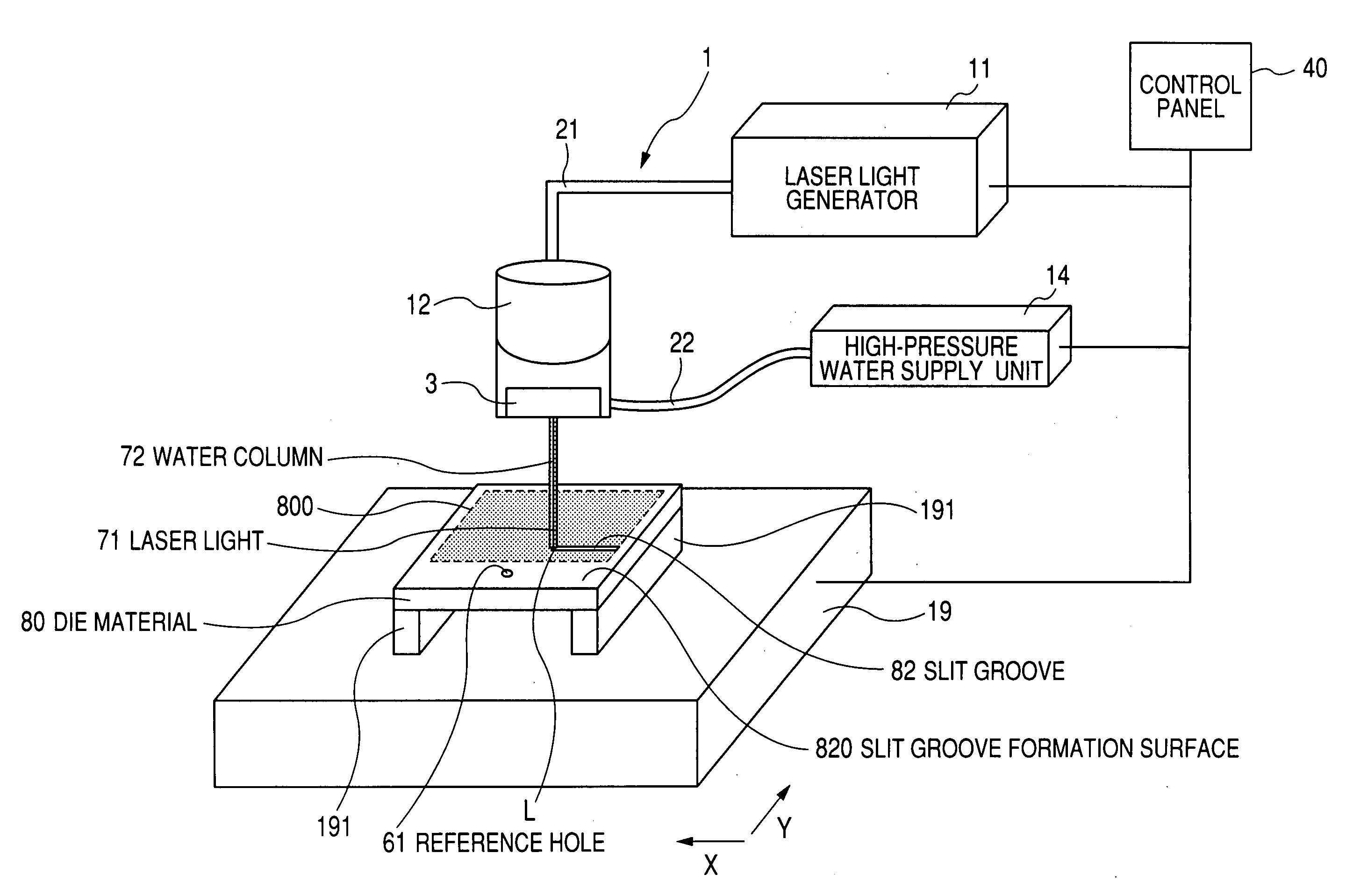
[0043]A description will be given of the method of producing a molding die for use in producing, such as extruding and molding, honeycomb structure bodies made of ceramic material according to the first embodiment of the present invention with reference to FIGS. 1A and 1B to FIG. 8.

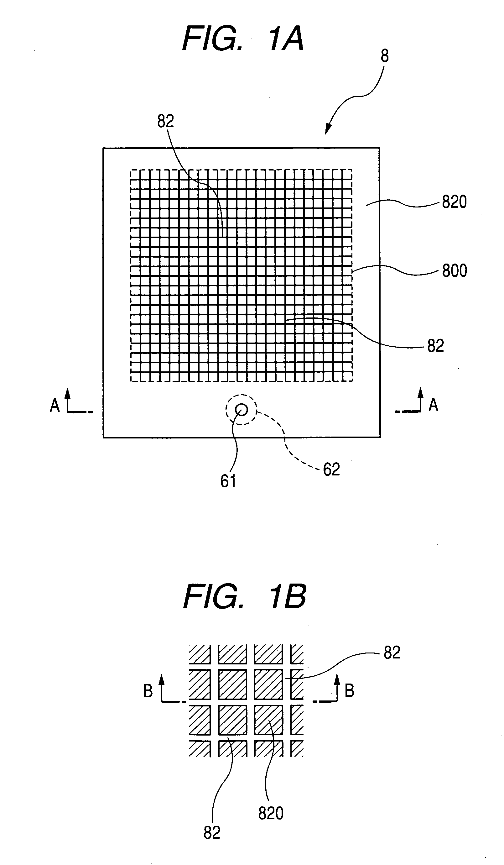
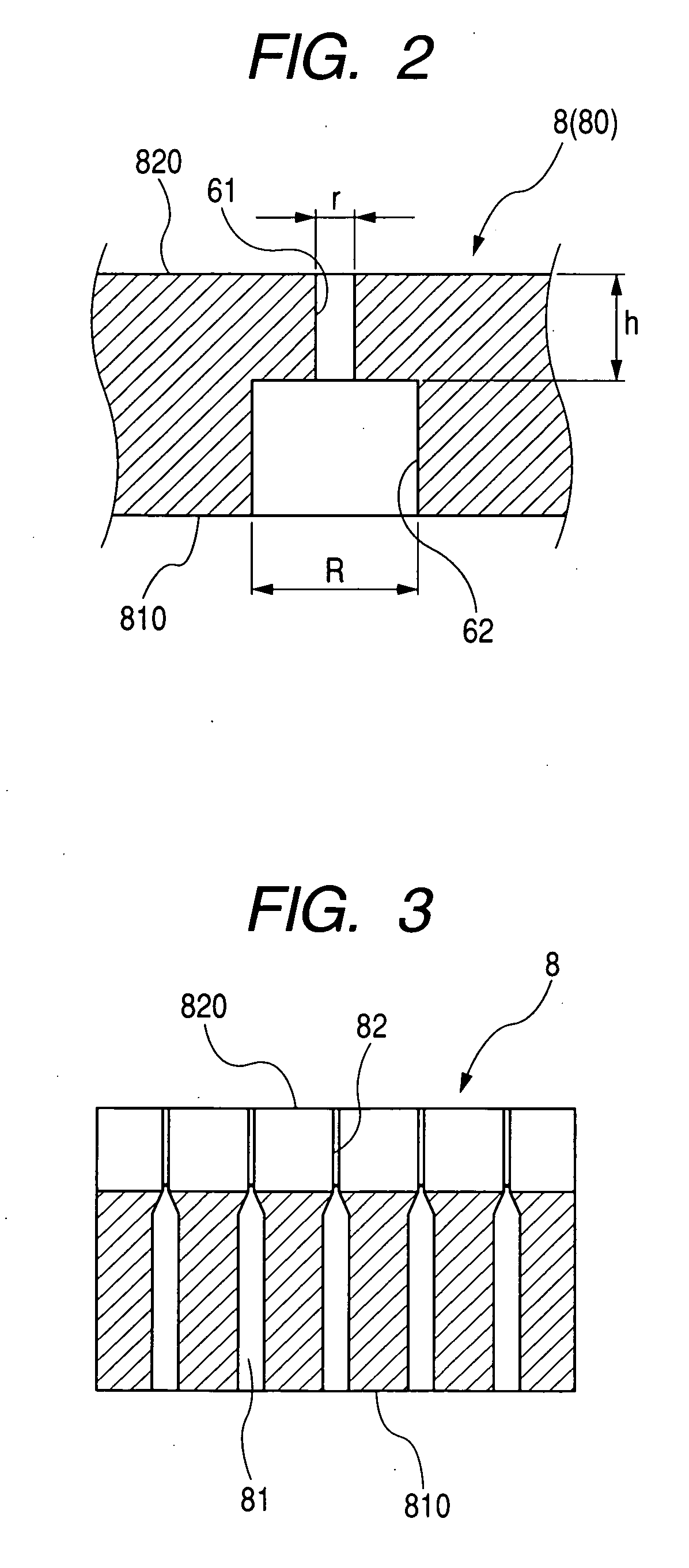
[0044]FIG. 1A is an explanation view of a slit groove formation surface 820 of a workpiece as a target die plate material, with which the molding die 8 for use in producing honeycomb structure bodies is produced by the method according to the present invention. FIG. 1B is an enlarged view of the slit groove formation surface 820 in the workpiece shown in FIG. 1A. FIG. 2 is a sectional view of the slit groove formation surface 820 of the workpiece along the A-A line designated by arrows shown in FIG. 1A. FIG. 3 is a sectional view of the slit groove formation surface 820 of the workpiece along the B-B line designated by arrows shown in FIG. 1B.

[0045]As shown in FIG. 1A and FIG. 3, a plurality of feed holes...

modification example

[0084]FIG. 8 is an explanation view of the reference hole and its peripheral configuration in the workpiece to be worked in the method according to the first embodiment of the present invention.

[0085]In the method according to the first embodiment of the present invention described above, although the reference hole 61 is so formed in the slit groove formation surface 820 of the workpiece 80 that it communicates with the escape hole 62 whose diameter is larger than that of the reference hole 61. The present invention is not limited by this configuration, for example, it is possible to form only the reference hole 61 which penetrates the workpiece 80 without forming the escape hole 62. This configuration can also achieve the same effect.

[0086]As shown in FIG. 3 and FIG. 8, although the reference hole 61 has a same diameter along its depth direction, it is possible for the reference hole 61 to have a taper shape or a shape in which the middle part thereof has a smaller diameter, when ...

second embodiment

[0087]A description will be given of the method of producing the molding die for producing (such as extruding and molding) honeycomb structure bodies made of ceramic material according to the second embodiment of the present invention with reference to FIG. 9.

[0088]FIG. 9 is an explanation view of a reference hole 61 formed in a supplemental nozzle part 31-1 (as a reference hole formation member) and its peripheral configuration in the workpiece 80 to be worked in the method according to the second embodiment of the present invention. As shown in FIG. 9, an engagement penetration hole 63 is formed in the workpiece 80 instead of the reference hole 61. The diameter of the engagement penetration hole 63 corresponds to that of the outer periphery of the nozzle part 31 shown in FIG. 5. A supplemental nozzle part 31-1 mutually engages the engagement penetration hole 63 so that the supplemental nozzle part 31-1, the engagement penetration hole 63, and the slit groove formation surface 820 ...


PUM

PropertyMeasurementUnit
Diameteraaaaaaaaaa
Diameteraaaaaaaaaa
Widthaaaaaaaaaa

Abstract

In a method of producing a molding die for use in producing honeycomb structure bodies, a reference position is determined as a relative position on a workpiece between a pillar of a high-pressure water jet and a reference hole. The reference hole is penetratingly formed in a workpiece. The outer periphery of the pillar passes through the reference hole without contacting the inner wall and opening edge of the reference hole. A slit groove formation position is aligned with a pillar formation position by relatively shifting the pillar to the workpiece based on coordinate data where the reference position becomes its origin. Each slit groove is formed in the workpiece by supplying the pillar onto the slit groove formation position on the workpiece while irradiating and scanning a laser beam into the pillar of a high-pressure water jet many times along the slit groove formation position on the workpiece.

Description

CROSS-REFERENCE TO RELATED APPLICATION[0001]This application is related to and claims priority from Japanese Patent Application No. 2007-29574 filed on Feb. 8, 2007, the contents of which are hereby incorporated by reference.BACKGROUND OF THE INVENTION[0002]1. Field of the Invention[0003]The present invention relates to a method of producing a molding die for use in producing (such as extruding and molding) honeycomb structure bodies made of ceramic material.[0004]2. Description of the Related Art[0005]A molding die for use in producing, namely, extruding and molding ceramic honeycomb structure bodies made of ceramic material has a plurality of slit grooves arranged in grid-like shape (or lattice shape). There have been proposed various related-art techniques for making such slit grooves on the molding die. In more recent years, a water jet laser slitter or cutting method is known, for example, disclosed in Japanese patent laid open publications No. JP 2002-301581 and No. JP 2003-11...

Claims


Application Information

Patent Timeline
IPC IPC(8): B28B11/12B23K26/36B23K26/00B23K26/02B23K26/364B28B3/26
CPCB23K26/041B23K26/1417B28B2003/203B26F3/004B23P15/243B23K26/042B23K26/146
Inventor FUKUSHIMA, TAKESHI
Owner DENSO CORP
Learn More