
Phase alignment mechanism for minimizing the impact of integer-channel interference in a phase locked loop

a phase locking loop and integer channel technology, applied in the field of data communication, can solve the problems of not being able to tolerate output of pll, and achieve the effect of minimizing the impact of interferen

Inactive Publication Date: 2008-08-14
TEXAS INSTR INC
View PDF5 Cites 65 Cited by
  • Summary
  • Abstract
  • Description
  • Claims
  • Application Information

AI Technical Summary

Benefits of technology

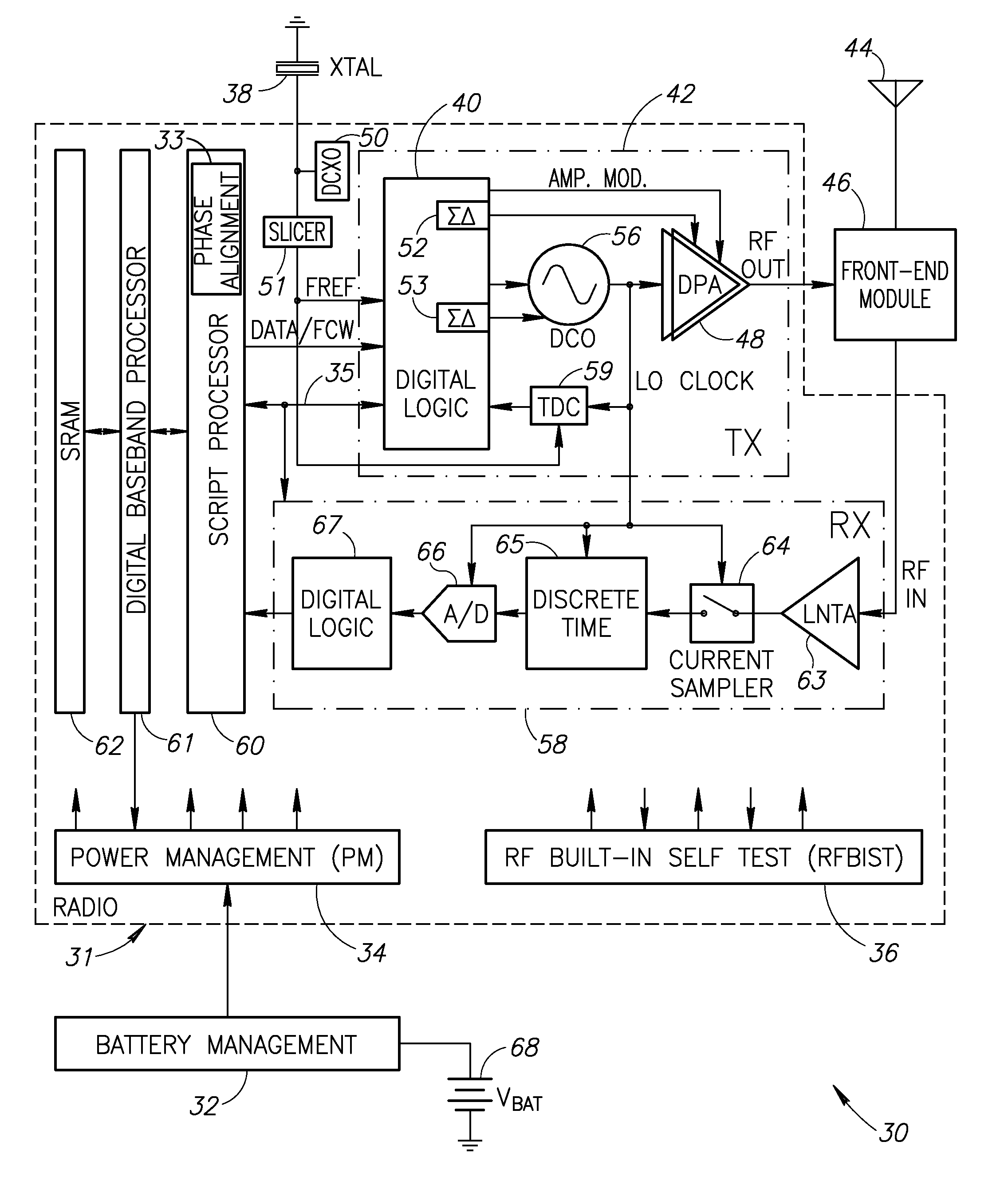
[0027]The present invention is a novel and useful apparatus for and method of minimizing the jitter induced onto the input reference signal of a phase locked loop (PLL) by an RF interfering signal that is located around an integer multiple of that reference frequency. The impact of such interference on the output of the PLL may manifest itself in the form of excessive phase error or distortion, which a receiver based on it would often not tolerate due to degradation in reception quality that this could result in, and which a transmitter would not tolerate due to the possible violation of the transmitter's spectral mask and / or its modulation quality requirements (e.g., peak phase error and RMS phase error). The mechanism of the present invention is based on alignment (or adjustment) of the phase of the interfering RF signal (or signals) with respect to that of the reference signal, such that the interference impact is minimized.
[0028]The mechanism of the invention mitigates the impact of the aggressing signal within the victim circuitry by active means that ensure that the impact of the interference is tolerable. This is contrary to passive interference mitigation techniques wherein the impact of the interference is mitigated through the reduction in the power of the interfering aggressor, or through shielding or filtering provided on the victim side, where the interference is experienced. A common example of active interference mitigation is the active cancellation or suppression of interference in receiver front-end circuitry based on adaptation to the interference. In the mechanism of the present invention, the interference is mitigated actively by measuring the phase relationship between the aggressor and victim signals and actively and instantly shifting it to an optimal phase relationship, where the resultant performance degradation is minimal.
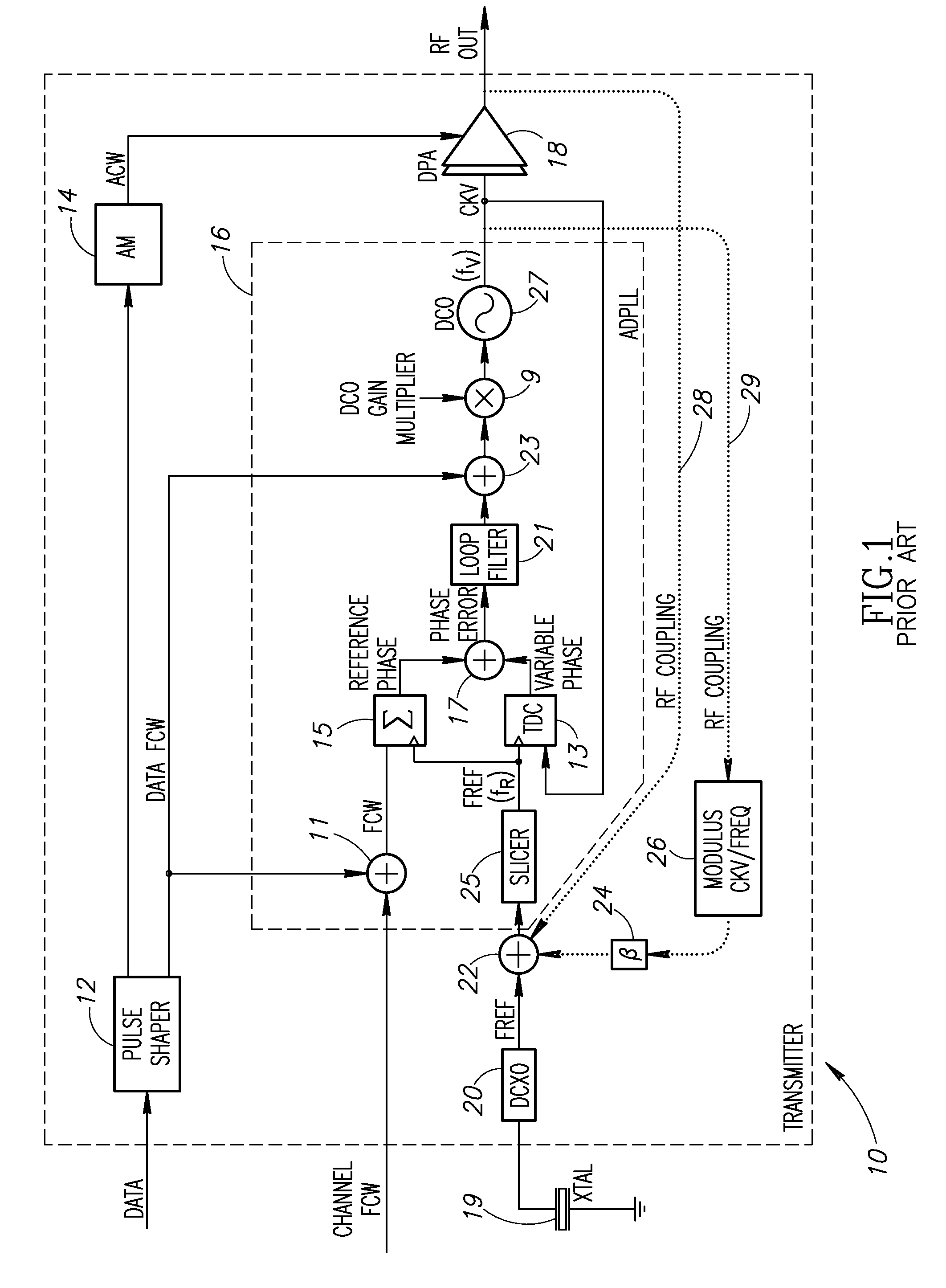
[0029]In particular, the mechanism addresses the phenomenon of DCXO jitter caused by a phase modulated GSM RF signal (or the second harmonic of it) transmitted on an integer channel (N×FREF), such that the impact on the victimized reference frequency signal is tolerable. The interference impact is phase-dependent because the phase adjustment controls both the power of the resultant jitter signal and its spectral content, potentially shifting it to higher frequencies, where the low-pass filtering in the phase domain within the ADPLL can offer better suppression.

Problems solved by technology

The impact of such interference on the output of the PLL may manifest itself in the form of excessive phase error or distortion, which a receiver based on it would often not tolerate due to degradation in reception quality that this could result in, and which a transmitter would not tolerate due to the possible violation of the transmitter's spectral mask and / or its modulation quality requirements (e.g., peak phase error and RMS phase error).
This is contrary to passive interference mitigation techniques wherein the impact of the interference is mitigated through the reduction in the power of the interfering aggressor, or through shielding or filtering provided on the victim side, where the interference is experienced.

Method used


Image

  • Phase alignment mechanism for minimizing the impact of integer-channel interference in a phase locked loop
  • Phase alignment mechanism for minimizing the impact of integer-channel interference in a phase locked loop
  • Phase alignment mechanism for minimizing the impact of integer-channel interference in a phase locked loop

Examples


Embodiment Construction

Notation Used Throughout

[0060]The following notation is used throughout this document.

TermDefinitionACAlternating CurrentACWAmplitude Control WordADCAnalog to Digital ConverterADPLLAll Digital Phase Locked LoopAMAmplitude ModulationASICApplication Specific Integrated CircuitAVIAudio Video InterfaceBISTBuilt-In Self TestBMPWindows BitmapCMOSComplementary Metal Oxide SemiconductorCPUCentral Processing UnitDBBDigital BasebandDCDirect CurrentDCODigitally Controlled OscillatorDCXODigitally Controlled Crystal OscillatorDPADigitally Controlled Power AmplifierDRACDigital to RF Amplitude ConversionDRPDigital RF Processor or Digital Radio ProcessorDSLDigital Subscriber LineDSPDigital Signal ProcessorEDGEEnhanced Data Rates for GSM EvolutionEDREnhanced Data RateEPROMErasable Programmable Read Only MemoryFCWFrequency Command WordFIBFocused Ion BeamFMFrequency ModulationFPGAField Programmable Gate ArrayGMSKGaussian Minimum Shift KeyingGPSGlobal Positioning SystemGSMGlobal System for Mobile commu...


PUM


Abstract

A novel and useful apparatus for and method of minimizing the impact of interference on the phase error performance in a phase locked loop (PLL) at integer channels by adjustment of the phase of the interfering signal such that its impact on the reference signal is minimized. Phase control is achieved by use of the digital architecture of the ADPLL and its insensitivity to an arbitrary phase bias introduced between its digitally represented output and reference phase signals. The optimal phase relationship for each integer channel is determined through a calibration procedure in which the phase is swept and the optimal phase is recorded. Before the transmission of a payload on an integer channel, the phase relationship between the output RF signal and the input reference signal is adjusted to the value found to be optimal for that frequency, based on the values previously recorded during the calibration procedure.

Description

REFERENCE TO PRIORITY APPLICATION[0001]This application claims priority to U.S. Provisional Application Ser. No. 60 / 889,334, filed Feb. 12, 2007, entitled “Dithering of Frequency Reference Through Bond Wires”, incorporated herein by reference in its entirety.FIELD OF THE INVENTION[0002]The present invention relates to the field of data communications and more particularly relates to an apparatus for and method of phase alignment for minimizing the impact of integer-channel interference in a phase locked loop (PLL).BACKGROUND OF THE INVENTION[0003]A current trend in modern radio design is the attempt to continually increase the level of integration. The integration of wireless transceivers within digital Systems on Chips (SoCs), driven by cost reduction demands and the advances in technology, creates various challenges related with the coexistence of the various functions within the SoC. The many analog and digital functions, which operate in proximity and share the same die, potenti...

Claims


Application Information

Patent Timeline
IPC IPC(8): H04L7/00
CPCH03L2207/50H03L7/1806
Inventor ELIEZER, OREN E.ENTEZARI, MANOUCHEHRSTASZEWSKI, ROBERT B.BHATARA, SUMEER
Owner TEXAS INSTR INC
Learn More