Method of manufacturing rotor and exhaust turbo-supercharge incorporating the rotor

a technology of exhaust turbo-supercharger and rotor, which is applied in the direction of liquid fuel engine, vessel construction, marine propulsion, etc., can solve the problems of insufficient strength of the joined part, cracks in the joined part, and the stiffness of the joined part is lowered, so as to prevent the strength of the shaft from being lowered, the effect of high temperature resistance and no lowering of the strength

Inactive Publication Date: 2008-08-21
MITSUBISHI HEAVY IND LTD
View PDF20 Cites 16 Cited by
  • Summary
  • Abstract
  • Description
  • Claims
  • Application Information

AI Technical Summary

Benefits of technology

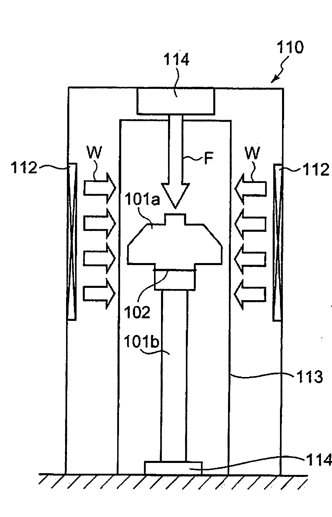
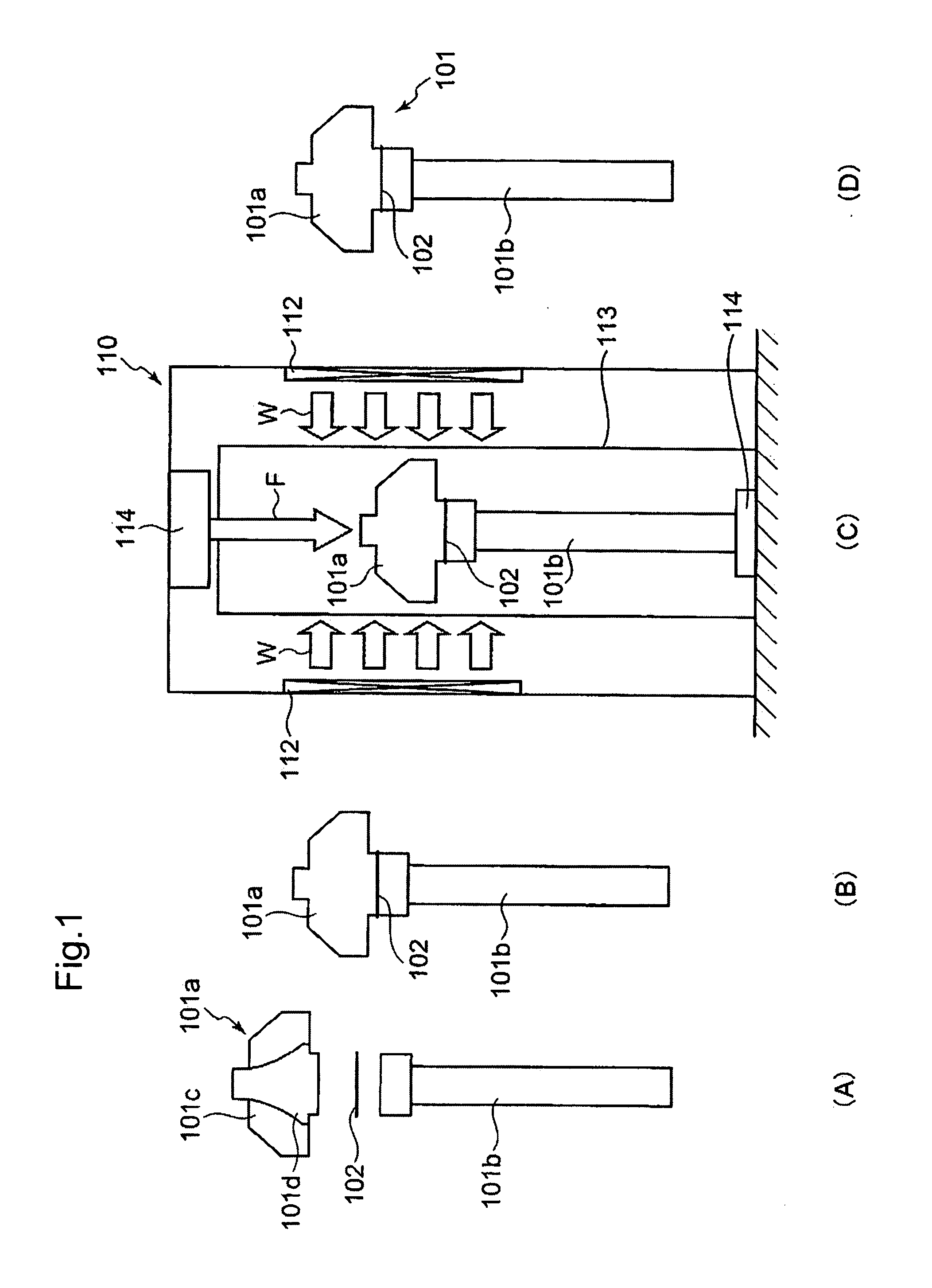
[0017]According to the present invention, infrared radiation is irradiated onto the wheel side part when a wheel and a shaft which constitute a rotor such as a turbine rotor are joined to each other by brazing, and accordingly, their surfaces to be joined are heated up to a temperature in a range from 1,000 to 1,080 deg. C. with the use of a transmitted heat in order to join the surfaces by brazing. Thus, the joint by brazing can be completed without heating the shaft up to a temperature not lower than 1,100 deg. C., as has been carried out in the prior art, thereby it is possible to prevent the strength of the shaft from being lowered by the heating. It is noted that the wheel is made of metal having a high temperature resistance greatly higher than that of the shaft, no lowering of the strength is caused even though it is heated up to a temperature not lower than 1,100 deg. C.
[0018]Thus, it is possible to eliminate the necessity of heat-treating the shaft part in order to make up for a decrease in the strength, as has been made in the prior art, after brazing, and accordingly, the man hours for manufacturing rotors including turbine rotors can be reduced due to elimination of the heat-treatment.
[0019]Further, since the infrared radiation is irradiated onto the side part of the wheel which is therefore heated up, occurrence of local temperature rise of the wheel as experienced in high frequency heating in the prior art can be restrained even though a wheel having a complicated configuration is heated by infrared radiation, and accordingly, there can be uniformly heated the wheel so as to prevent conventionally experienced lowering of the strength of the joined part due to such a fact that Fe is diffused in the shaft, being caused by heating at a high temperature of 1,100 deg. C., the Fe reacting with C added in the Ti—Al, resulting in the formation of an extremely fragile carbide in the interface in the joined part. Thus, the strength of the joined part by brazing can be enhanced.
[0020]Further, the shaft can be maintained at a temperature which is relatively lower than the heating temperature not lower than 1,100 deg. C. as used in the prior art, and accordingly, a residual stress in the vicinity of the joined part after cooling of the rotor having been joined, can be reduced, thereby it is possible to prevent occurrence of disadvantages including cracking of a part in the vicinity of the joined part, and breakage of the joined part by an external force. It is noted that the linear expansion coefficient of the wheel is extremely less than that of the shaft, and accordingly, a residual stress existing therein after cooling is extremely small.
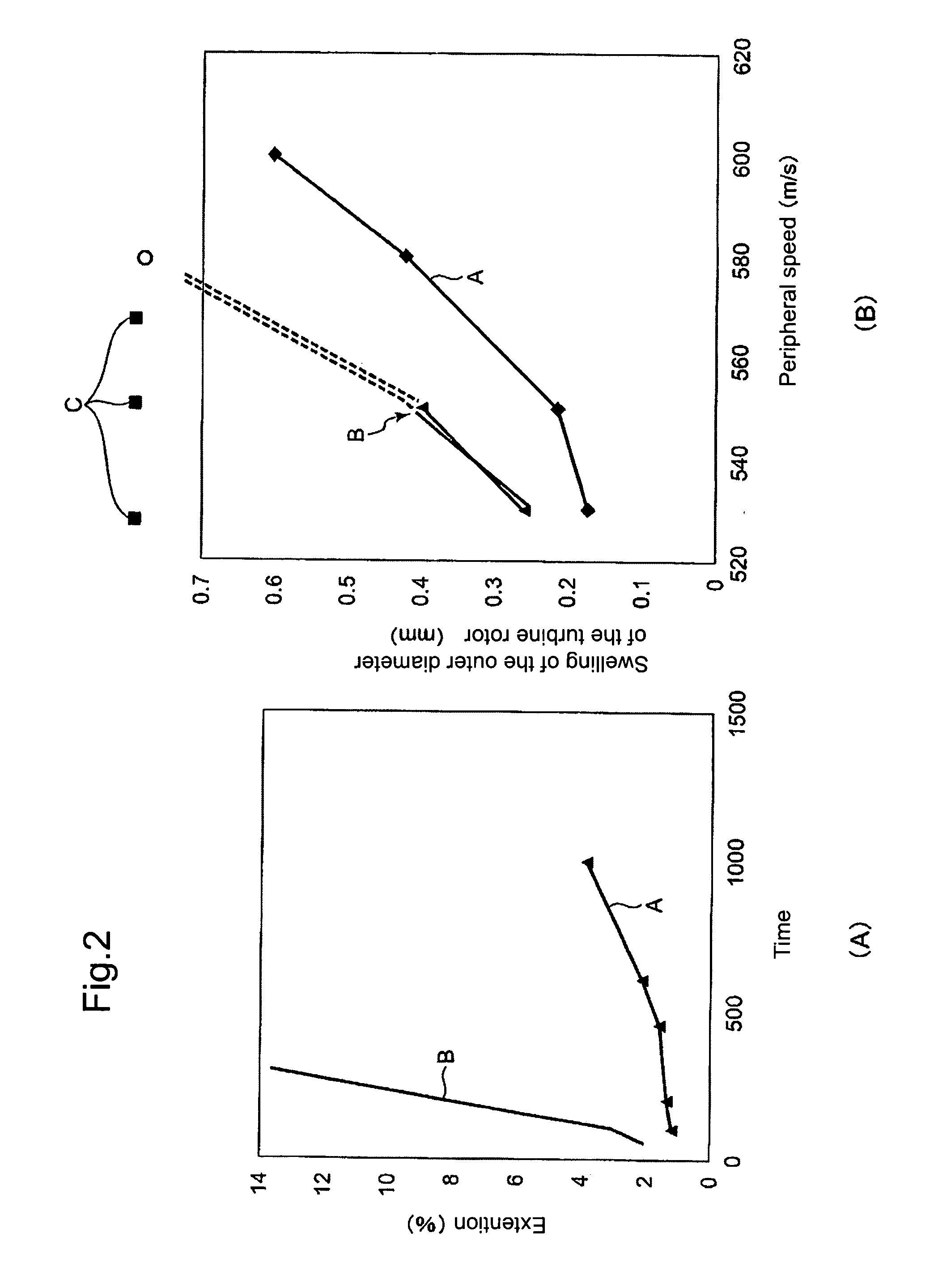
[0021]Further, since the wheel of each of rotors including the above-mentioned rotor, which is made of Ti-Ai group alloy, contains 0.05 to 0.012 (Wt. %) of C as one of components therein, by setting the additive amount of C to a value in the above-mentioned range, the creep strength thereof can be enhanced without lowering the toughness of the wheel, and accordingly, the rotor can be prevented from diametrically swelling even though it is used in exhaust gas at a high temperature which is not lower than 950 deg. C., thereby it is possible to prevent breakage of the rotor during operation at a high temperature.
[0022]Thus, it is possible to enhance the durability and the reliability of rotors including a turbine rotor.

Problems solved by technology

Thus, the toughness of the joined part thereof is lowered, that is, it is likely to cause such a disadvantage that the strength of the joined part becomes insufficient.
Further, although only the shaft alone is high-frequency heated as stated above, a large residual stress is generated in the joined part thereof after cooling thereof since the linear expansion coefficient of the material of the shaft is large, and accordingly, since the joined part is fragile as stated above, there would be possibly caused such a disadvantage that the joined part cracks due to the residual stress or the joined part is broken by an external force.

Method used


Image

  • Method of manufacturing rotor and exhaust turbo-supercharge incorporating the rotor
  • Method of manufacturing rotor and exhaust turbo-supercharge incorporating the rotor
  • Method of manufacturing rotor and exhaust turbo-supercharge incorporating the rotor

Examples


Embodiment Construction

[0027]Explanation will be hereinbelow made of an embodiment of the present invention with reference to the accompanying drawings. It is noted that dimensions, materials, configurations, relative arrangement and the like of components described in this embodiment are merely exemplified, and is not intended to limit the technical scope of the present invention thererby alone unless otherwise specified.

[0028]FIG. 3 is a sectional view illustrating a variable delivery type exhaust turbo-supercharger incorporating a turbine rotor to which the present invention is applied, and being sectioned along the rotating axis thereof.

[0029]Referring to FIG. 3, there are shown a turbine casing 10, a scroll 11 which are formed in a spiral-like shape in the outer peripheral part of the turbine casing 10, a radial flow turbine rotor 101 arranged coaxial with a compressor 8 and having a turbine shaft 101b which is rotatably journalled to a bearing housing 13 through the intermediary of bearings 16, a co...


PUM

PropertyMeasurementUnit
temperatureaaaaaaaaaa
Wt. %aaaaaaaaaa
strengthaaaaaaaaaa

Abstract

Provided are a method of manufacturing a brazed rotor composed of a wheel and a shaft joined to the former by brazing, having a durability and a reliability which can be enhanced without increasing the manufacturing man hours, and a turbine rotor for an exhaust turbo-supercharger. The wheel having a disc portion formed at its outer periphery with blades, and a rod-like shaft are arranged in a furnace, being opposed to each other at their surfaces to be joined with a brazing solder being interposed therebetween, and infrared radiation is irradiated onto a side part of the wheel so as to heat the surfaces to be joined up to a temperature in a range from 1,000 to 1,080 deg. C. in order to melt the brazing solder, thereby the wheel and the shaft are joined by brazing to each other at their surfaces to be joined.

Description

BACKGROUND OF THE INVENTION[0001]1. Field of the Invention[0002]The present invention relates to a method of manufacturing a rotor which is adapted to be used as a turbine rotor in an exhaust turbo-supercharger for an internal combustion engine and which is composed of a wheel having a disc portion formed at its periphery with blades, and a shaft formed in a rod-like shape and joined to the wheel by brazing, and is also relates to an exhaust turbo-supercharger utilizing the above-mentioned rotor.[0003]2. Description of the Related Art[0004]In a relatively small-sized exhaust turbo-supercharger used in a vehicle engine or the like, there has been, these years, used a turbine rotor in which a wheel having a disc portion formed at its periphery with blades is joined to a shaft formed in a rod-like shape by brazing.[0005]A Patent Document 1 (Japanese Patent Laid-Open No. H06-159085) discloses a technology of a method of manufacturing the above-mentioned brazed turbine rotor, as an examp...

Claims


Application Information

Patent Timeline
Patent Type & Authority Applications(United States)
IPC IPC(8): F01D25/28B23P15/04F01D5/02F01D5/30
CPCF01D5/026Y10T29/49316F01D5/063
Inventor NITTA, KENJITETSUI, TOSHIMITSU
Owner MITSUBISHI HEAVY IND LTD
Why Eureka
Try Eureka