
Process for tungsten nitride deposition by a temperature controlled lid assembly

Inactive Publication Date: 2008-08-28
APPLIED MATERIALS INC
View PDF101 Cites 36 Cited by
  • Summary
  • Abstract
  • Description
  • Claims
  • Application Information

AI Technical Summary

Benefits of technology

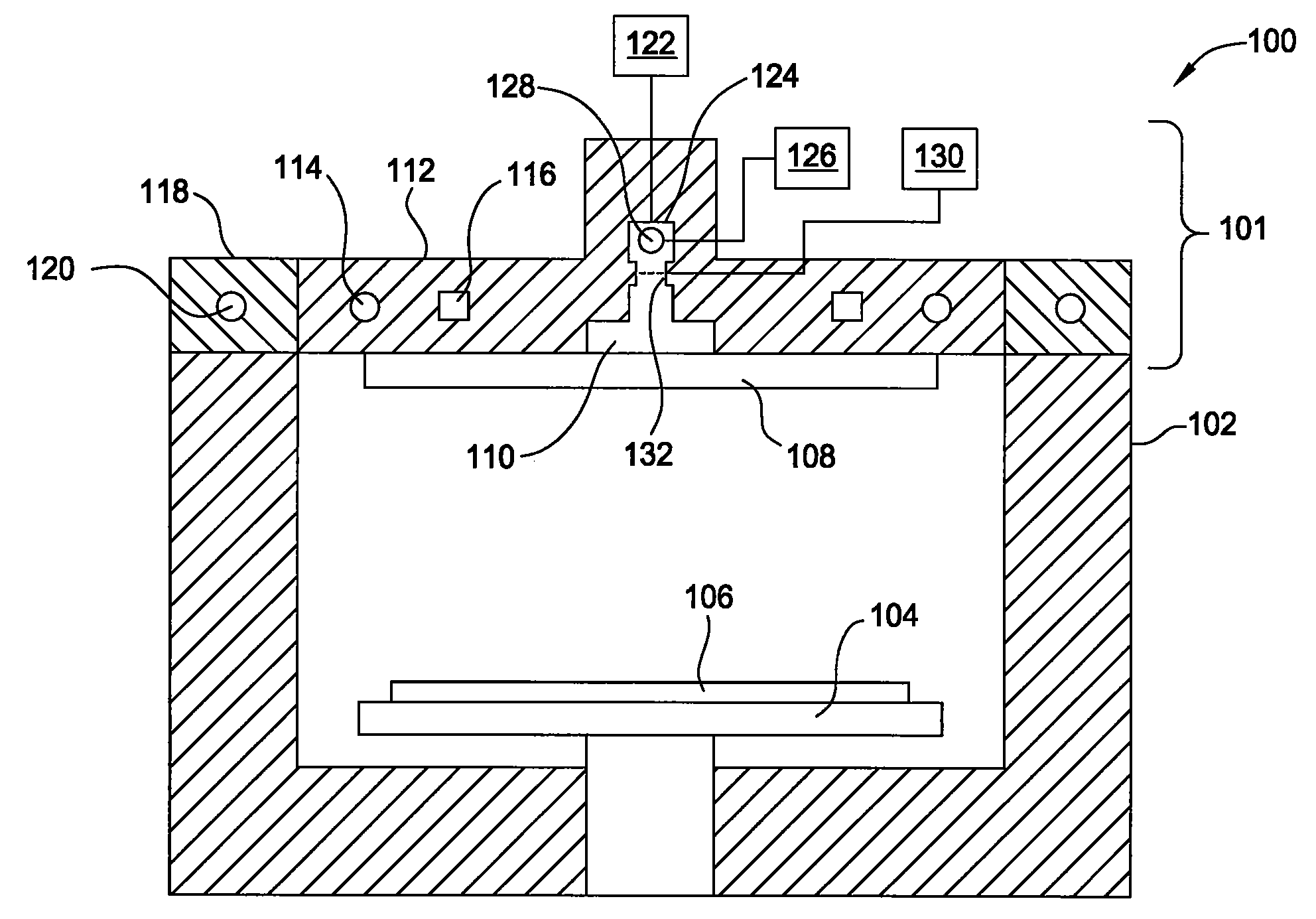
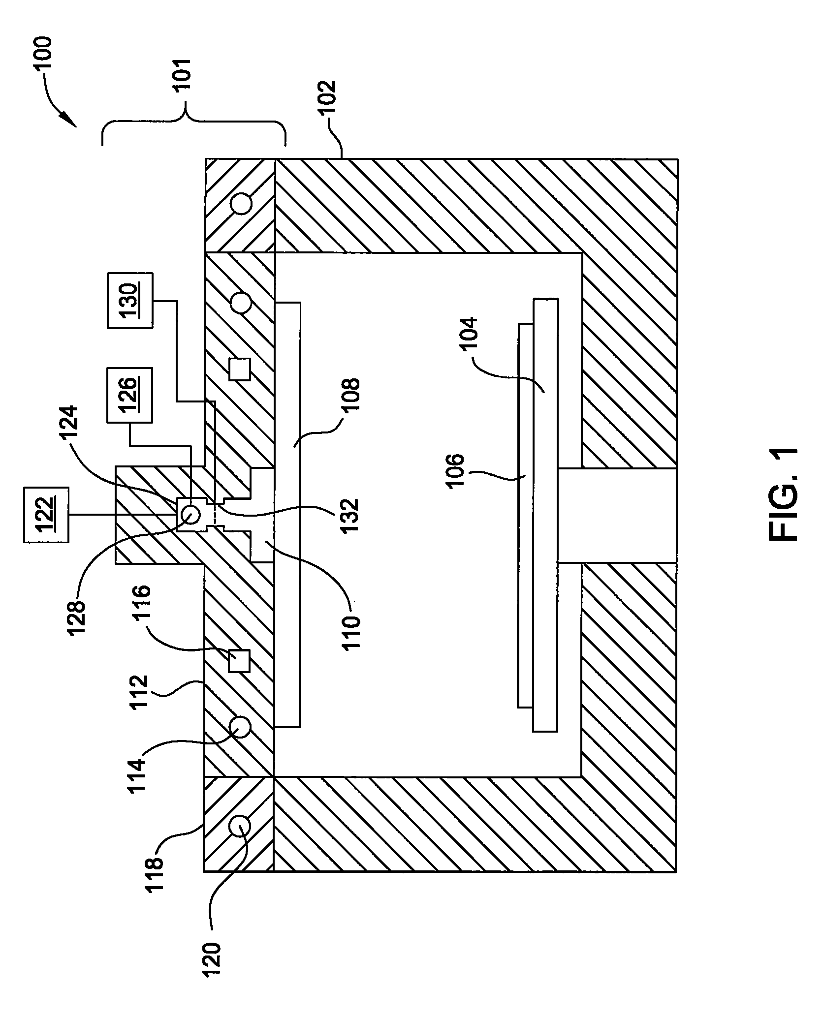
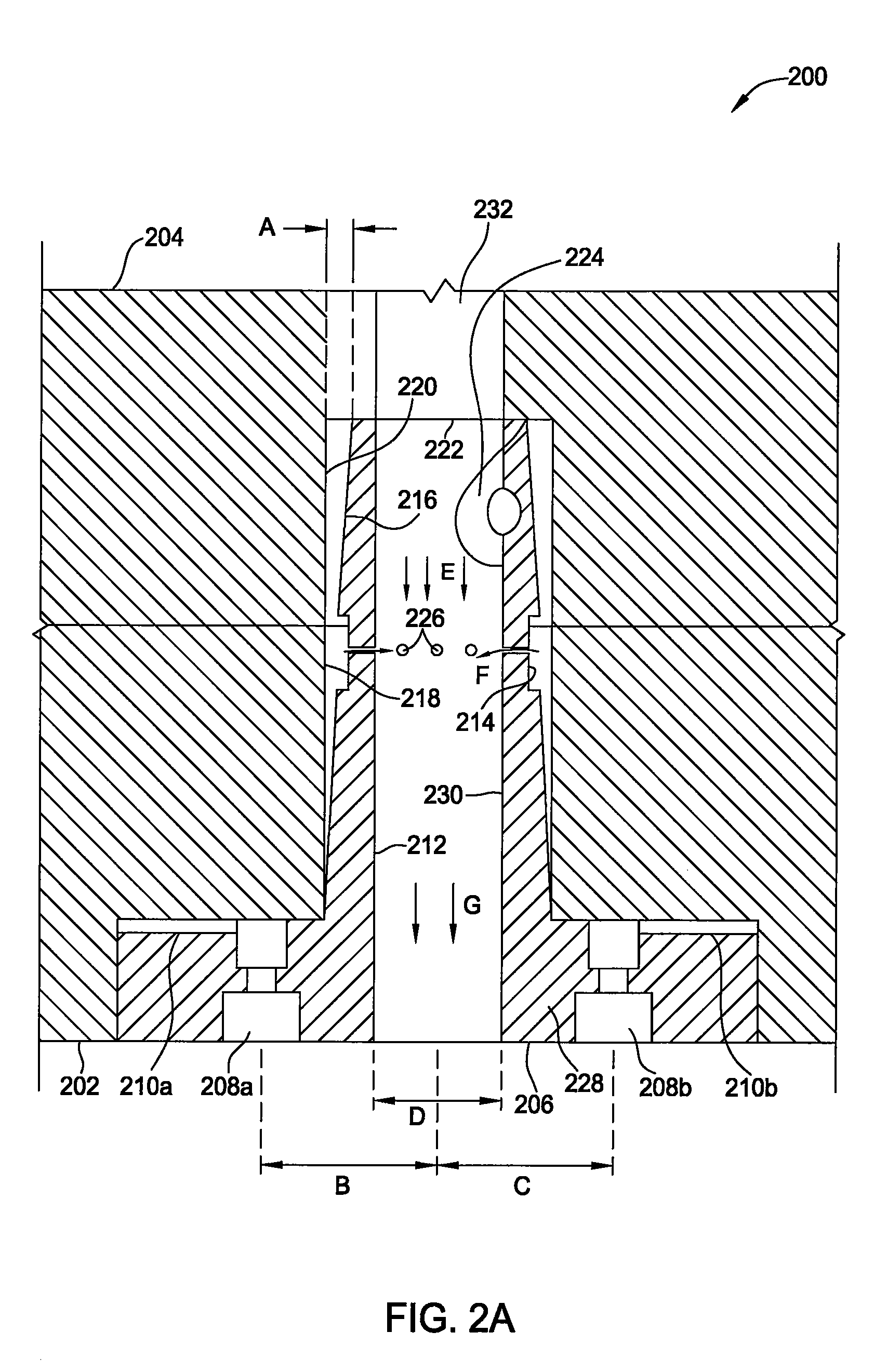
[0019]In other embodiments, an angled mixer and a lid assembly that may be utilized on a processing chamber are disclosed herein. The lid assembly may have both heating elements and cooling channels to permit rapid heating and cooling of the chamber lid so that multiple depositions may occur within the same processing chamber at different temperatures. The mixer may be angled to be disposed within a central area of the lid assembly. The mixer may have an opening at the top to permit cleaning gas to enter the processing chamber, a second opening to permit introduction of a first deposition gas, and a third opening to permit introduction of a second deposition gas perpendicular to the flow of the first deposition gas so that the first and second deposition gases effectively mix within the mixer before being exposed to the substrate.

Problems solved by technology

Without annealing, the silicon will ultimately diffuse into the tungsten forming a non-uniform layer of tungsten silicide.
Unfortunately, silicon diffuses into the tungsten forming tungsten silicide.
Unfortunately, the above described process results in the formation of contaminant particles in the form of solid byproducts.
During temperature fluctuations within the chamber, the deposits flake off the walls and contaminate the wafer.
As a result, the diffusion barrier properties of the tungsten nitride are compromised.
In addition, tungsten nitride films deposited by the traditional method tend not to adhere very well to the substrate upon which they are deposited.

Method used


Image

  • Process for tungsten nitride deposition by a temperature controlled lid assembly
  • Process for tungsten nitride deposition by a temperature controlled lid assembly
  • Process for tungsten nitride deposition by a temperature controlled lid assembly

Examples


Embodiment Construction

[0035]Embodiments of the invention provide a processing chamber for depositing a material by vapor deposition. In one embodiment, the processing chamber includes a lid assembly attached to a chamber body, wherein the lid assembly contains a lid plate, a showerhead, a mixing cavity, a distribution cavity, and a resistive heating element contained within the lid plate. In one example, the resistive heating element is configured to provide the lid plate at a temperature within a range from about 120° C. to about 180° C., preferably, from about 140° C. to about 160° C., more preferably, from about 145° C. to about 155° C., such as about 150° C. The mixing cavity is in fluid communication with a tungsten precursor source and a nitrogen precursor source, wherein the tungsten precursor source generally contains tungsten hexafluoride and the nitrogen precursor source generally contains ammonia.

[0036]Embodiments of the apparatuses and processes as described herein are useful to deposit tungs...


PUM

PropertyMeasurementUnit
Temperatureaaaaaaaaaa

Abstract

Embodiments of the invention provide processes for vapor depositing tungsten-containing materials, such as metallic tungsten and tungsten nitride. In one embodiment, a method for forming a tungsten-containing material is provided which includes positioning a substrate within a processing chamber containing a lid plate, heating the lid plate to a temperature within a range from about 120° C. to about 180° C., exposing the substrate to a reducing gas during a pre-nucleation soak process, and depositing a first tungsten nucleation layer on the substrate during a first atomic layer deposition process within the processing chamber. The method further provides depositing a tungsten nitride layer on the first tungsten nucleation layer during a vapor deposition process, depositing a second tungsten nucleation layer on the tungsten nitride layer during a second atomic layer deposition process within the processing chamber, and exposing the substrate to another reducing gas during a post-nucleation soak process.

Description

CROSS-REFERENCE TO RELATED APPLICATIONS[0001]This application claims benefit of U.S. Ser. No. 60 / 887,142 (APPM / 011741L), filed Jan. 29, 2007, and U.S. Ser. No. 60 / 944,085 (APPM / 011741L02), filed Jun. 14, 2007, which are herein incorporated by reference in their entirety.BACKGROUND OF THE INVENTION[0002]1. Field of the Invention[0003]Embodiments of the invention generally relate to a temperature controlled lid assembly for a processing chamber and a method for depositing tungsten-containing materials on a substrate by vapor deposition processes.[0004]2. Description of the Related Art[0005]Modern integrated circuits contain large numbers of transistors. These transistors are generally field effect transistors that contain a source region and a drain region with a gate electrode located in between the source and drain regions.[0006]A typical gate structure contains a thin polysilicon electrode that lies on top of a thin layer of gate oxide such as silicon oxide. The gate electrode and ...

Claims


Application Information

Patent Timeline
IPC IPC(8): H01L21/44
CPCC23C16/14C23C16/34C23C16/45523C23C16/4411C23C16/45512C23C16/4401
Inventor GELATOS, AVGERINOS V.LEE, SANG-HYEOBYUAN, XIAOXIONGUMOTOY, SALVADOR P.CHANG, YUTZU, GWO-CHUANRENUART, EMILYLIN, JINGLAI, WING-CHEONGLE, SANG Q.
Owner APPLIED MATERIALS INC
Learn More