
Process for recovering lower carbon olefins from product gas for production of olefins

a technology of olefins and product gas, which is applied in the direction of cold treatment separation, liquefaction, lighting and heating apparatus, etc., can solve the problems of serious shortage of starting material resources, increasing the demand for low carbon olefins, etc., and achieves the effect of saving energy and cos

Active Publication Date: 2008-09-04
CHINA PETROCHEMICAL CORP +1
View PDF13 Cites 12 Cited by
  • Summary
  • Abstract
  • Description
  • Claims
  • Application Information

AI Technical Summary

Benefits of technology

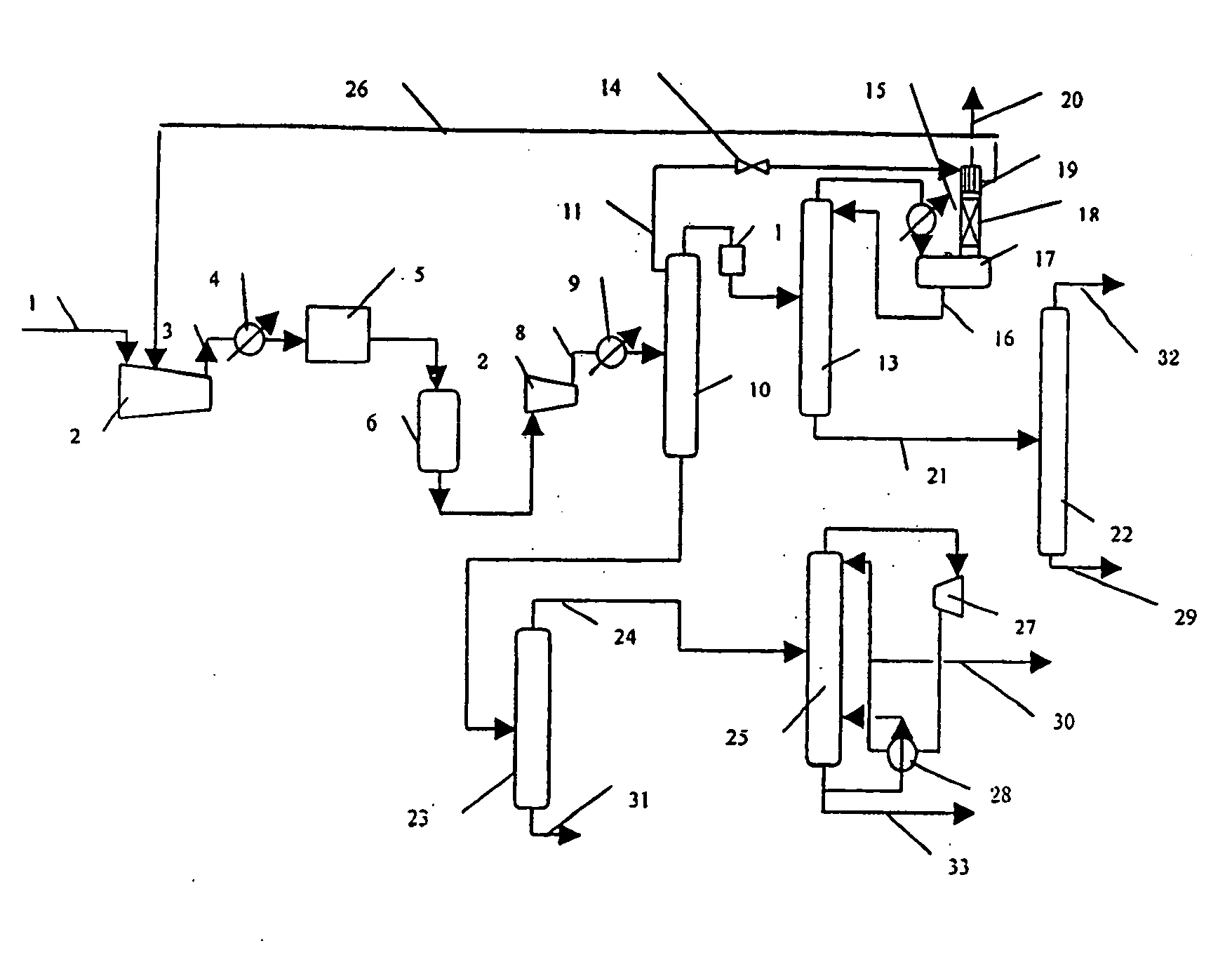
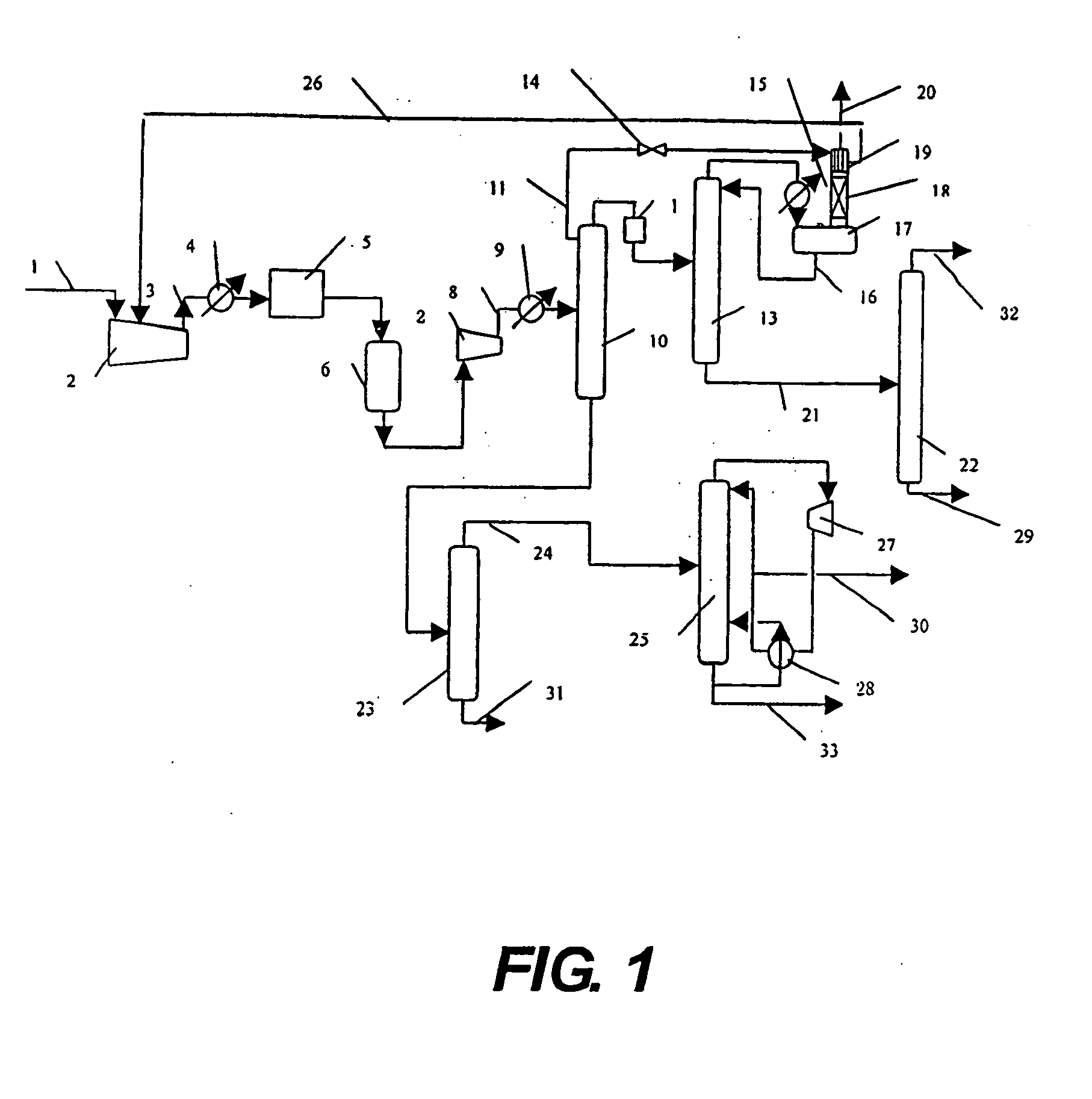
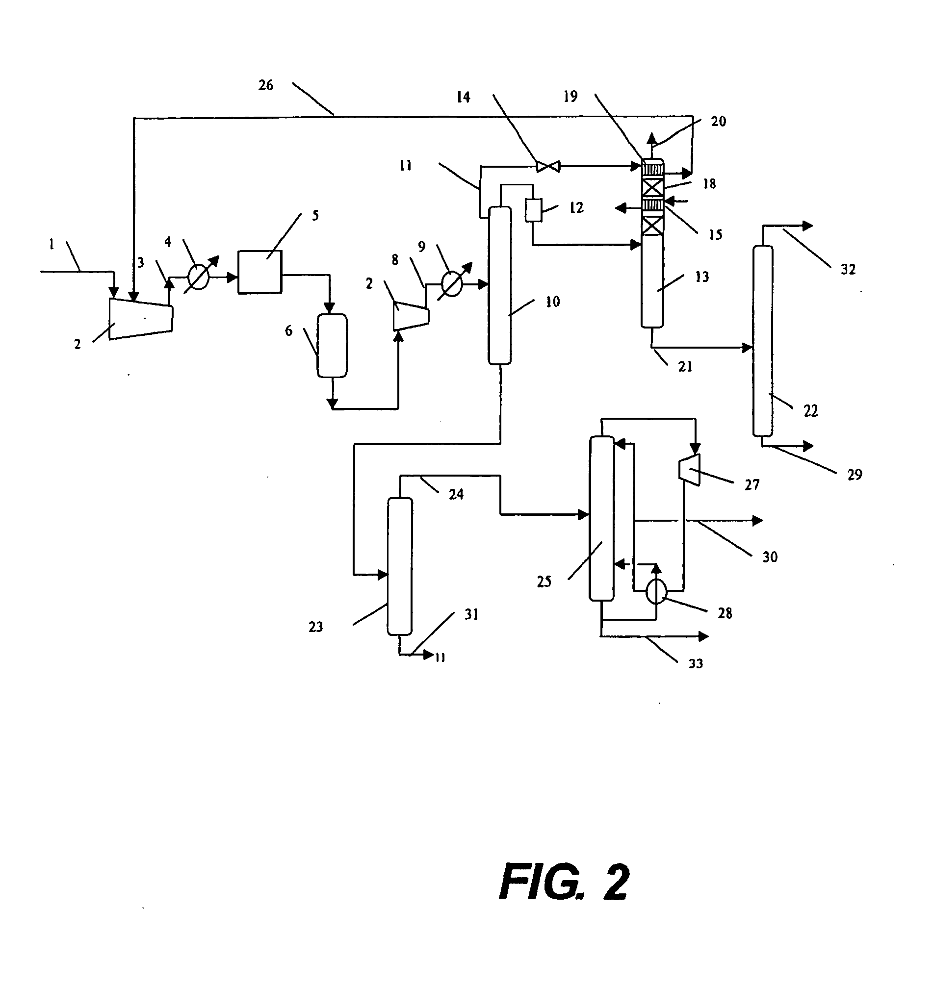
[0021]In order to achieve better separation effects, one preferred embodiment involves that said ethylene recovering device further comprises a rectification column section 18 directly linking with the demethanizing column reflux tank 17. The uncondensed tail gas in the reflux tank 17 is fed into the. rectification column section 18. Various internal column components may be used inside the rectification column section 18, e.g. fillings, float valves and the like. Generally, the operation temperature of said rectification column section 18 ranges from −37 to −98° C. Said plate type condenser 19 is set up at the top of the rectification column section 18. The ethylene recovering device consisting of the rectification column section 18 and the condenser 19 is used to further recover ethylene in the uncondensed gas by using the fractionation principle, so as to increase the ethylene recovery rate.
[0028](4) Ethylene rectification system. The materials at the bottom of the demethanizing column 13 are fed into the ethylene rectification system 22. At the top of the ethylene rectification system 22 is obtained the ethylene product in a polymerizable grade, which has an ethylene content of higher than 99.9 mol %. Ethane obtained at the bottom of the ethylene rectification column 22 can be delivered out as a product or incorporated into the fuel system. Since there are only C2 components in the materials fed into the ethylene rectification column 22, open-type heat pump technique may be used in the ethylene rectification column, if required by the consumer, to reduce the energy consumption.
[0030]In a specific embodiment, if the common engineering system is deficit in steam, the system of the combination of the rectification column with the open-type heat pump technique may be used as the propylene rectification system to reduce the energy consumption of the device. Meanwhile, the combination with propylene refrigeration compressor may also be used to reduce the compressor units. Specifically, the gas at the top of the propylene rectification column 25 is firstly fed into the heat pump compressor 27 so as to increase the pressure to a sufficient extent and to condense propylene in the reboiler 28. A part of condensed propylene is taken out, and the remaining is refluxed back to the top of the column. Therefore, the propylene rectification column needs no steam to provide heat for the reboiler.
[0034]1. feeding part or all of the tail gas in said demethanizing column reflux tank into the ethylene recovering device, to further recover ethylene in the uncondensed gas by using the fractionation principle and to increase the ethylene recovery rate, which may be higher than 99.5%; and
[0035]2. after throttling and pressure-reducing, using the liquid materials from the deethanizing column reflux tank or ethylene rectification column as the coolant of said ethylene recovering device; and vaporized coolant returns to a suitable site of the processing gas compressor without any separate ethylene refrigeration compressor, so as to save energy and cost.

Problems solved by technology

It is learned that the demand for low carbon olefins is increasing, but the starting material resources, e.g. naphtha, light diesel oil and so on, for the production of ethylene is confronted with serious shortage.
It can be seen that three processing compressors and a propylene refrigeration compressor are required in said ethylene recovering technology, which increases the equipment investment.
Meanwhile, said uncondensed gas is discharged in said technology so as to lose a small amount of ethylene.
Accordingly, the ethylene recovery rate is not satisfactory, and generally about 95-97%.

Method used


Image

  • Process for recovering lower carbon olefins from product gas for production of olefins
  • Process for recovering lower carbon olefins from product gas for production of olefins
  • Process for recovering lower carbon olefins from product gas for production of olefins

Examples


examples

[0071]According to the scheme as shown in FIG. 1, low carbon olefins were recovered from the MTO product gas. The composition (mol %) of the MTO product gas fed into the separation system was shown in Table 1, wherein the temperature thereof was 41° C., and the pressure was 135 kPaA.

TABLE 1Composition of the FeedstockComponentCOMethaneethyleneethanepropylenepropaneC4C5 and higherContent0.232.3061.064.6124.420.925.530.93(mol %)

[0072]The scheme simulation for the scheme of FIG. 1 was conducted by using the general PROVISION 6.0 scheme simulation software from Simsci, to obtain the simulation computation data results as shown in Table 2.

[0073]The computation results showed that the recovery rate of ethylene may achieve 99.5% by using the process of the present invention to separate the MTO product gas.

TABLE 2DischargedGas at theFluid at theFluid at theTail gas in theMTOat thetop of thebottom of thebottom of thedemethanizingproductend of thedeethanizingdeethanizingdemethanizingcolumnEth...


PUM

PropertyMeasurementUnit
temperatureaaaaaaaaaa

Abstract

The present invention concerns a process for recovering lower carbon olefins from MTO or DTO product gas. Said process primarily comprises the product gas compressing, pre-deethanizing, demethanizing and ethylene recovering apparatus, depropanizing column, ethylene rectification column, propylene rectification column and the like. In addition, the process of the present invention needs no independent ethylene cooling system, and the ethylene recovery rate may achieve 99.5%.

Description

TECHNICAL FIELD [0001]The present invention relates to a process for recovering low carbon olefins from a product gas obtained from an olefin conversion device. More specifically, the present invention concerns a process for recovering ethylene and propylene from the product gas from the methanol to olefin device and / or dimethyl ether to olefin device.BACKGROUND ART [0002]It is learned that the demand for low carbon olefins is increasing, but the starting material resources, e.g. naphtha, light diesel oil and so on, for the production of ethylene is confronted with serious shortage. The methanol to olefin (hereinafter referred to as MTO) or dimethyl ether to olefin (hereinafter referred to as DTO) technique, therefore, has drawn much attention. MTO or DTO technique is a technology for producing low carbon olefins, such as ethylene, propylene and the like, by using coal-based or natural gas-based synthesized methanol or dimethyl ether as the starting materials and by means of a fluid...

Claims


Application Information

Patent Timeline
Patent Type & Authority Applications(United States)
IPC IPC(8): F25J3/00
CPCC07C7/09F25J3/0219F25J3/0233F25J3/0238F25J3/0242F25J2200/90F25J2210/04F25J2270/90F25J2210/12F25J2215/62F25J2245/02C07C11/04Y02P30/20Y02P30/40C07C11/02
Inventor WANG, ZHENWEISHENG, ZAIHANGZHAO, XUELIANG
Owner CHINA PETROCHEMICAL CORP
Learn More