High-Pressure Gas Compressor And Method Of Operating A High-Pressure Gas Compressor

a gas compressor and high-pressure technology, applied in the direction of mechanical equipment, pumps, liquid fuel engines, etc., can solve the problems of increasing the weight and overall size of the compressor, the practicability of maintaining the hertzian pressure below the desired limit, and the weight of the roller is too large to achieve the effect of increasing the hardness of the surface, reducing the coefficient of friction, and good sealing

Active Publication Date: 2008-09-04
WESTPORT FUEL SYST CANADA INC
View PDF20 Cites 57 Cited by
  • Summary
  • Abstract
  • Description
  • Claims
  • Application Information

AI Technical Summary

Benefits of technology

[0022]The gas compressor preferably comprises a free-floating piston. An advantage of the free-floating piston design is that it reduces the number of components that require precise alignment. That is, the piston, which is reciprocable within the cylinder bore, does not have to be precisely aligned with the roller tappet assembly that is reciprocable within a bearing sleeve. The feature has additional importance with the presently disclosed compressor because there is an additional seal for the pressure compensation chamber to prevent pressurized gas from leaking from the pressure compensation chamber to the cam case. The free-floating piston arrangement avoids the requirement of aligning the piston, stem and roller tappet assembly with each other, simplifying the manufacturing process and improving the operability and durability.
[0023]For multi-stage compressors, another advantage of the presently disclosed compressor with its free-floating pistons is that it can be less expensive to manufacture because the tappets for each of the stages can all be the same, with only the separately manufactured pistons having different diameters. This can also reduce the cost of spare parts and the number of spare parts kept in inventory.
[0026]The method can further comprise coating metal surfaces that interface with gas seals that comprise polytetrafluoroethylene. The coating is a thin film coating that increases surface hardness and reduces the coefficient of friction to lower than that of steel, providing a desirably smooth surface that helps to provide a good seal, and reduce the heat generated by friction between the seal and moving components such as the cylinder bore and the piston stem. In preferred embodiments, the coating is a diamond-like carbon thin film.
[0027]The disclosed compressor design is particularly advantageous for vehicular applications where it is important to provide a compressor with a compact and light weight design, that can be mechanically driven by the vehicle engine with high compressor speed, that takes advantage of the engine's water-cooled cooling system for compressor temperature management, and that has low parasitic volume to achieve a high volumetric efficiency.

Problems solved by technology

However, there are practical limits to the size of the roller because increasing the roller size also adds to the weight and overall size of the compressor.
For a compactly designed high-pressure compressor, it is usually impractical to maintain Hertzian pressure below desired limits by increasing roller size alone.
Higher Hertzian pressures beyond material limitations will increase wear and can result in mechanical failure and consequently reduce the service life of the rollers and / or cams if measures are not taken to reduce Hertzian pressure and / or increase the durability of the tappet roller and cam.
The gap between the piston and the cylinder bore that is between the piston head and the first piston ring seal also contributes to the parasitic volume.
The compressor does work to compress the gas in the parasitic volume to a high pressure, but at the end of the compression stroke, the piston can not move beyond its fully extended position to discharge the compressed gas from the parasitic volume of the compression chamber.
Furthermore, when the compressor piston retracts during the subsequent intake stroke to draw more gas into the compression chamber for the next compression stroke, new gas can not be drawn into the cylinder until after the compressed gas that was in the parasitic volume has expanded to the point where its pressure is less than the supply pressure of the gas that is to be drawn in through the inlet valve.
Therefore, a larger parasitic volume reduces the amount of new gas that can be drawn into the compression chamber on each subsequent intake stroke and this results in lower volumetric efficiency.
However, such arrangements can be more complicated and less efficient than an arrangement that employs a piston driven by a cam and roller tappet assembly, such as that disclosed by Miller et al.
However, a problem with this arrangement is that the piston, crosshead, and roller are fixedly attached to each other and each of these components must be aligned with another component: the piston with the cylinder, the crosshead with a guide, and the roller with the cam.
Consequently, the assembly taught by Miller would be expensive to manufacture because of the small manufacturing tolerances needed to for alignment of the piston in the cylinder, the crosshead in the guide, and the roller on the cam.
Miller also does not disclose an arrangement that would be suitable for operating with longer intervals between servicing and high durability.
For example, Miller does not disclose a means for lubricating the tappet roller assembly.
Furthermore, another important drawback of the compressor disclosed by Miller is that it does not provide a means for reducing the force acting on the piston resulting from the gas pressure in the compression chamber and consequently the Hertzian pressure between the roller and cam can be too high.
A problem specific to cam and roller tappet assemblies is wear of the cam and rollers, which is a problem that can be amplified in a compressor that is designed for handling high-pressure gases.
The Hertzian pressure is the contact pressure between the cam and roller, and damage or accelerated wear can result if the Hertzian pressure is too high.
Another disadvantage of excessively high forces resulting from high gas pressures in the compression chamber is that it can result in higher friction in the drive train and consequently, lower overall efficiency.
For compressors with variable intake gas pressure, such as compressors that are employed to pressurize gas supplied from a storage vessel, it can be difficult to guard against excessive Hertzian pressure because gas pressure in the compression chamber is variable, depending upon gas pressure in the storage vessel.
Such an arrangement is useful for a two-piston, two-stage compressor but is not suitable for other arrangements, such as a single-stage, single-piston compressor, or a three-stage, three-piston compressor.
Douville does not disclose a means for reducing Hertzian pressure that can be applied to each cylinder of both single and multi-piston compressors.

Method used


Image

  • High-Pressure Gas Compressor And Method Of Operating A High-Pressure Gas Compressor
  • High-Pressure Gas Compressor And Method Of Operating A High-Pressure Gas Compressor
  • High-Pressure Gas Compressor And Method Of Operating A High-Pressure Gas Compressor

Examples


Embodiment Construction

)

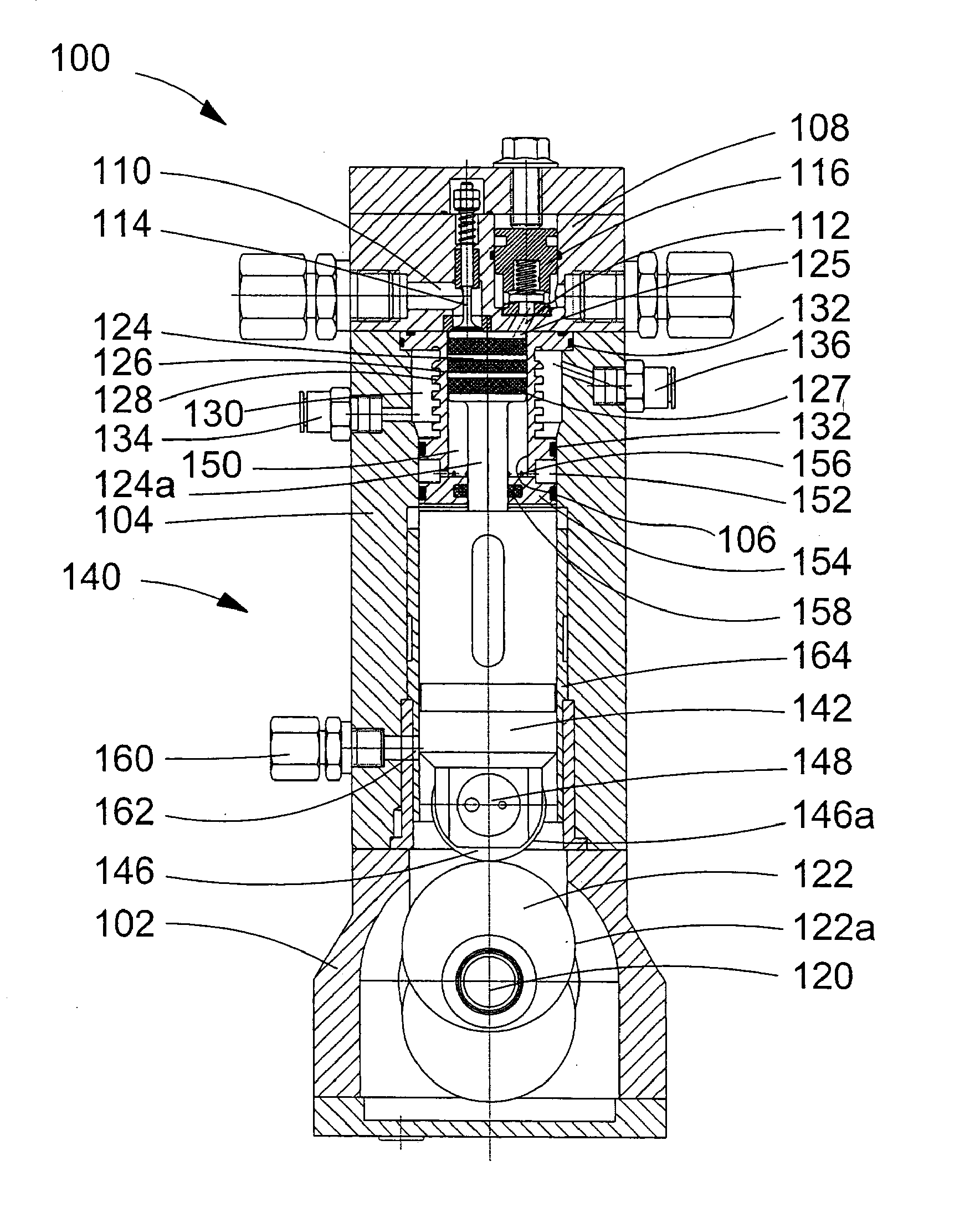
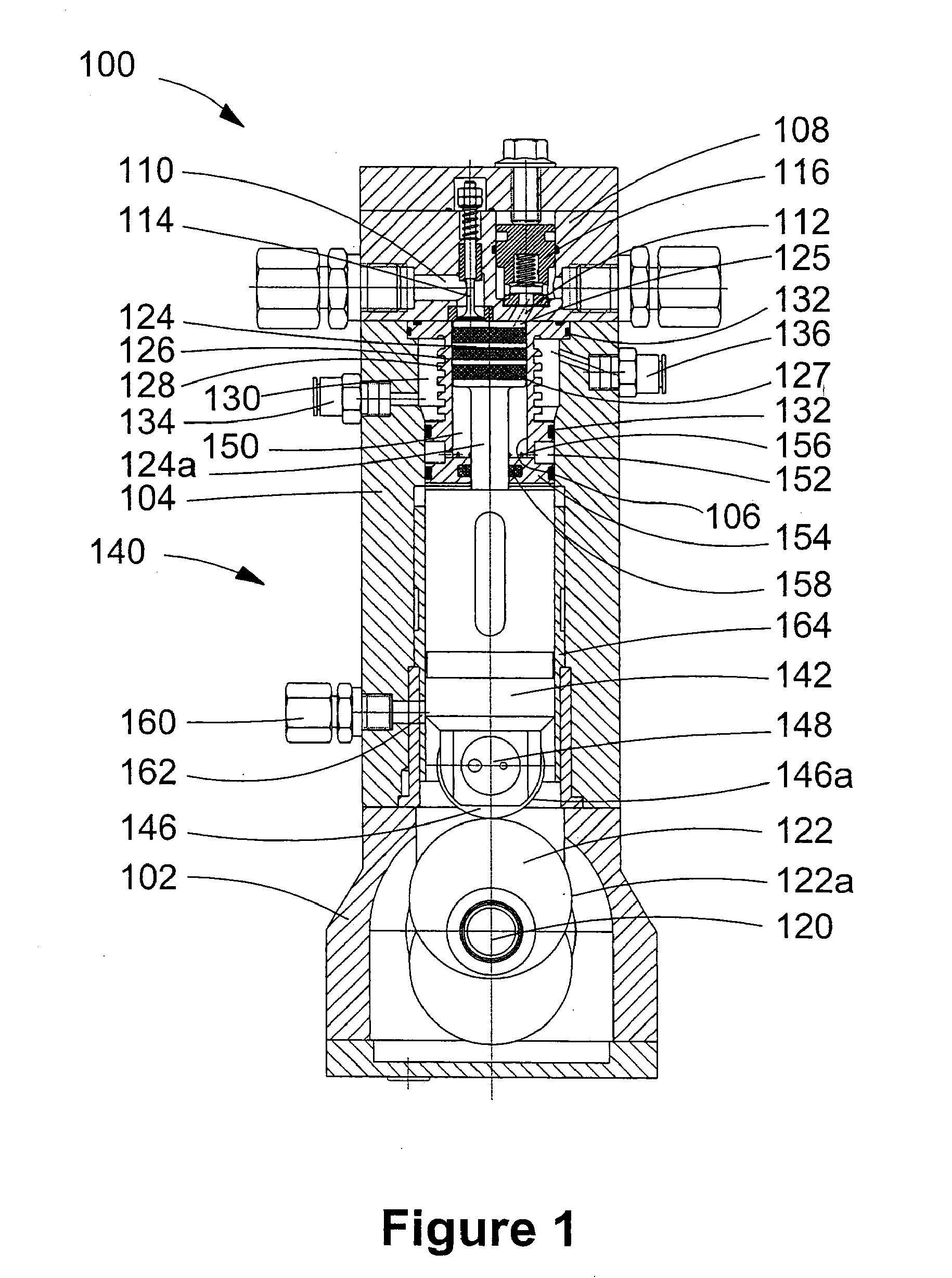
[0033]FIG. 1 is a section end-view of gas compressor 100. Compressor 100 can be adapted to compress various types of gases. In a particular application, the gases can be fuel gases, which are combustible and consumable as fuel in an internal combustion engine, such as gases selected from the group consisting of natural gas, a constituent of natural gas individually, propane, bio-gas, landfill gas, hydrogen gas, and mixtures of such gaseous fuels. In preferred embodiments for this application, the mechanical energy for driving compressor 100 can be supplied from the internal combustion engine that consumes the high-pressure gas discharged from compressor 100. For engines that inject the fuel gas directly into the combustion chamber when the engine's piston is near or at top dead center, it is necessary to supply the fuel gas at a high pressure in order to overcome the in-cylinder pressure and to achieve the desired fuel penetration and mixing. Gas compressor 100 is operable to disch...


PUM


Abstract

A high-pressure gas compressor comprises a single-acting cam driven piston with a pressure compensation chamber disposed between the piston and the cam. A roller tappet assembly transmits reciprocating motion from the cam to the piston. A pressurized gas directed to the pressure compensation chamber offsets forces acting on the piston from the compression chamber gas pressure, thereby reducing Hertzian pressure between the tappet roller and the cam. Overall efficiency and durability can be improved by reducing friction between compressor components, for example by employing thin film coatings to reduce friction, pressurized oil lubrication systems and higher cylinder bore diameter to piston stroke ratios. The service life of gas seals and compression efficiency can be improved by thermal management strategies, including liquid-cooled compressor cylinder liners and intercoolers between compression stages. Employing a poppet-style intake valve and reducing parasitic volume in the compression chamber can improve compressor volumetric efficiency.

Description

CROSS-REFERENCE TO RELATED APPLICATION(S)[0001]This application is a continuation of International Application No. PCT / CA2006 / 001276, having an international filing date of Aug. 3, 2006, entitled “High-Pressure Gas Compressor and Method of Operating a High-Pressure Gas Compressor”. International Application No. PCT / CA2006 / 001276 claimed priority benefits, in turn, from Canadian Patent Application No. 2,511,254 filed Aug. 4, 2005. International Application No. PCT / CA2006 / 001276 is hereby incorporated by reference herein in its entirety.FIELD OF THE INVENTION[0002]The present invention relates to a high-pressure gas compressor and a method of operating the compressor. In a particularly suitable embodiment, the disclosed apparatus relates to a gas compressor with a reciprocating single-acting piston with a drive mechanism that comprises a cam and roller tappet assembly and means for reducing the Hertzian pressure between the roller and cam.BACKGROUND OF THE INVENTION[0003]Engine-driven...

Claims


Application Information

Patent Timeline
Patent Type & Authority Applications(United States)
IPC IPC(8): F04B9/04F04B53/10F04B25/00F04B31/00F04B35/01F04B37/12
CPCF04B25/00F04B9/042
Inventor HILGER, ULRICHBARTUNEK, BERNDBLANK, MARTIN
Owner WESTPORT FUEL SYST CANADA INC
Why Eureka
Try Eureka