
Catheter With Microchannels For Monitoring The Concentration Of An Analyte In A Bodily Fluid

a technology of bodily fluid and catheter, which is applied in the field of diagnostics, can solve the problems of achieve the effect of reducing the dead volume of the catheter and short reaction time of such a system

Inactive Publication Date: 2008-09-04
ROCHE DIABETES CARE INC
View PDF7 Cites 108 Cited by
  • Summary
  • Abstract
  • Description
  • Claims
  • Application Information

AI Technical Summary

Benefits of technology

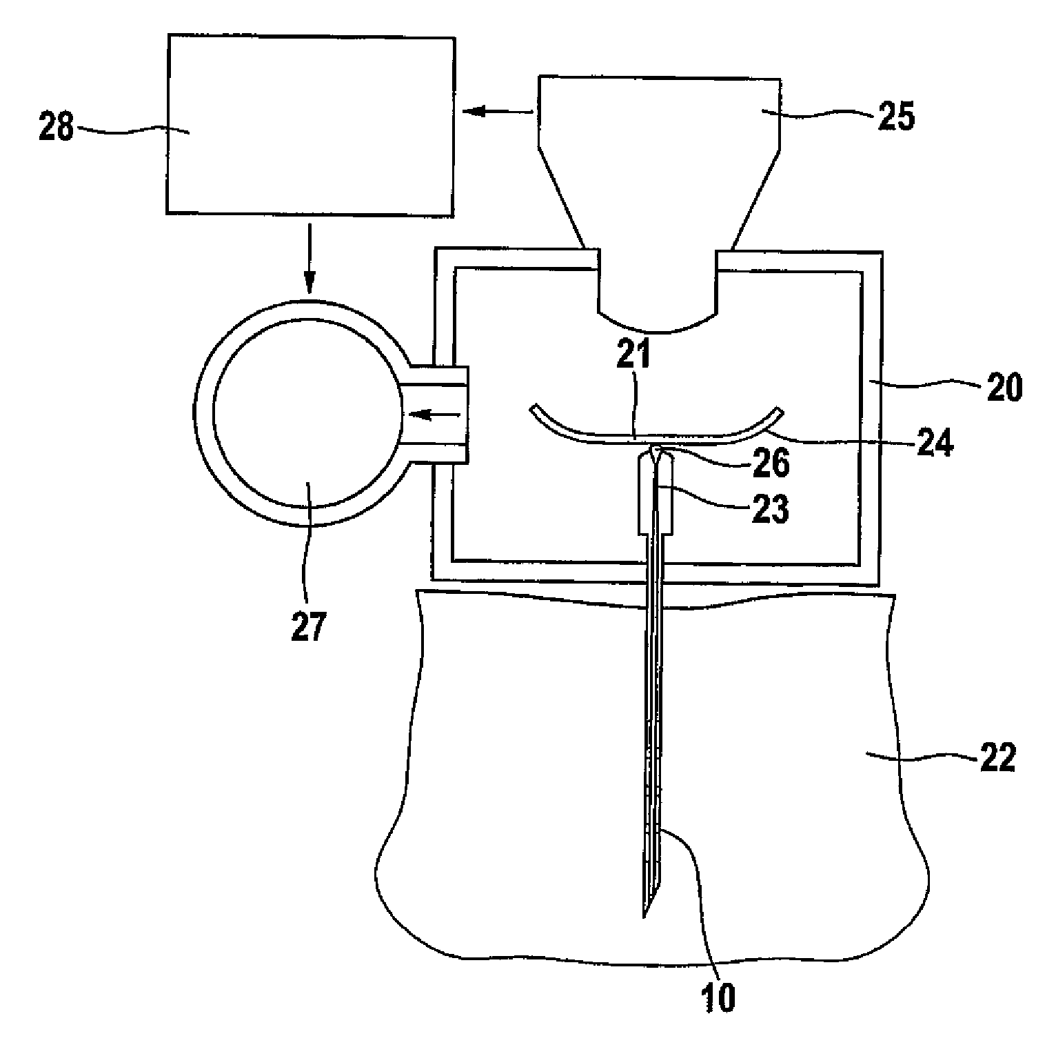
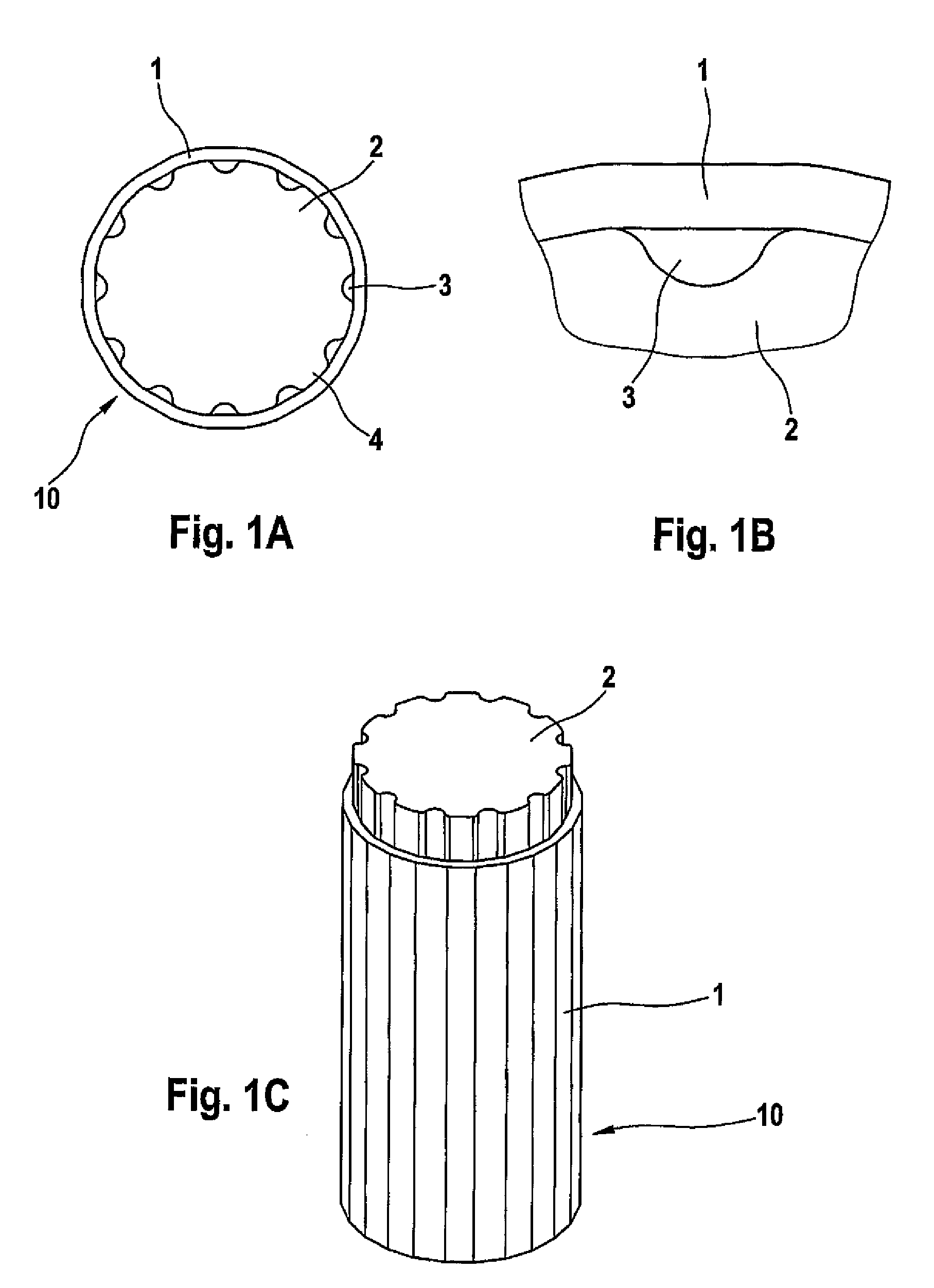
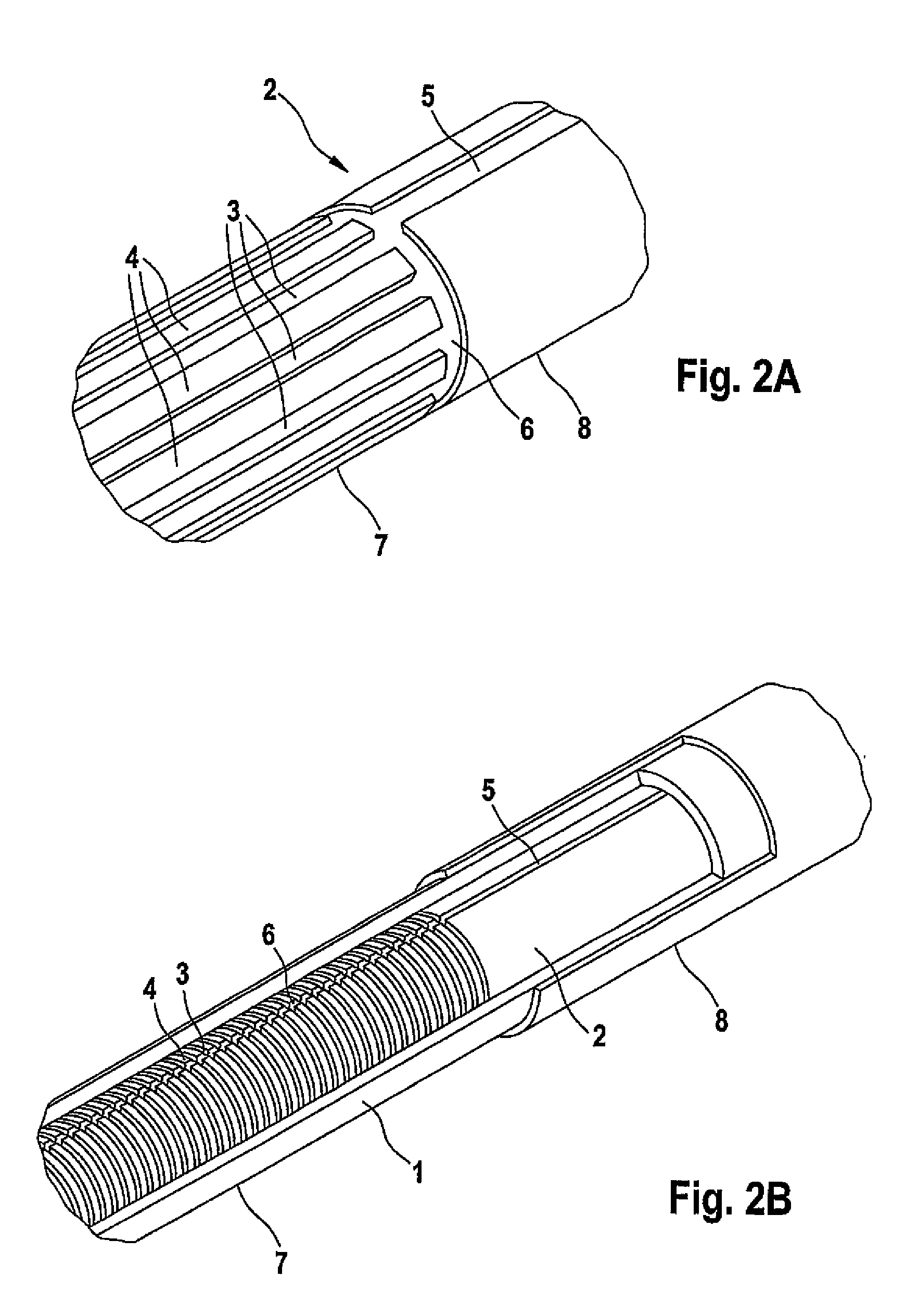
[0015]A catheter according to an embodiment of the present invention has an implantable distal area for the uptake of body fluids and a proximal area with an outlet opening and comprises a catheter casing having micro-openings which are permeable to at least part of the body fluid and at least partially retain corpuscular components, and a catheter core which is located in the catheter casing. The catheter core almost completely fills the inner volume of the catheter casing and in this manner reduces the dead volume of the catheter. However, the catheter core still leaves a hollow space open between the catheter casing and catheter core so that body fluid can be conveyed from the micro-openings in the distal area of the catheter casing to the outlet opening in the proximal area. The catheter core is located in the catheter casing during operation of the catheter.
[0039]Another method is to produce the micro-channels in the catheter core by photolithographic material build-up. In this process a radiation-sensitive polymeric lacquer a so-called resist is applied to the catheter core and the chemical solubility of the resist is changed by selective irradiation for example with UV light. As a result the resist has a radiation-dependent considerably lower or considerably higher resistance to solvents. This lithographic structuring allows a selective removal of structures that have been exposed differently and a subsequent further processing of the exposed surface of the support material. The exposure is carried out by means of special mask-based methods. In order to build up material the catheter core receives a metal deposition over the whole area after the development together with the remaining photoresist. After the remaining resist together with its overlying metal layer has been removed, the metal layer remains structured on the catheter core.

Problems solved by technology

Furthermore, the reaction time of such a system is very short because only a small volume has to be conveyed until the sample liquid reaches the sensor.

Method used


Image

  • Catheter With Microchannels For Monitoring The Concentration Of An Analyte In A Bodily Fluid
  • Catheter With Microchannels For Monitoring The Concentration Of An Analyte In A Bodily Fluid
  • Catheter With Microchannels For Monitoring The Concentration Of An Analyte In A Bodily Fluid

Examples


Embodiment Construction

[0060]For the purposes of promoting an understanding of the principles of the invention, reference will now be made to the embodiments illustrated in the drawings, which are described below. It will nevertheless be understood that no limitation of the scope of the invention is thereby intended. The invention includes any alterations and further modifications in the illustrated devices and described methods and further applications of the principles of the invention, which would normally occur to one skilled in the art to which the invention relates.

[0061]FIG. 1A shows a cross-section through an embodiment of a catheter (10) according to the present invention. The catheter (10) is composed of an assembly of a catheter casing (1) which in this case comprises a thin tube membrane and a catheter core (2) which for example comprises a metal wire into the circumference of which depressions (3) are incorporated. These depressions can either be produced by material ablation or by generating...


PUM

PropertyMeasurementUnit
widthaaaaaaaaaa
depthaaaaaaaaaa
diameteraaaaaaaaaa

Abstract

Catheter for monitoring the concentration of an analyte in a body fluid having an implantable distal area (7) for the uptake of body fluids and a proximal area (8) with an outlet opening (14), wherein the catheter comprises a catheter casing (1) having microopenings which are permeable to at least part of the body fluid and at least partially hold back corpuscular components, and a catheter core (2) which is located in the catheter casing (1). The catheter core preferably has a microstructure on its peripheral surface and / or the catheter casing has a microstructure on its inner wall which form a hollow space between the catheter core and catheter casing. Moreover the invention concerns a method for the manufacture of such a catheter.

Description

RELATED APPLICATION[0001]This application is related to and claims priority to International Patent Application Serial No. PCT / EP2006 / 001565, filed Feb. 21, 2006, the disclosure of which is expressly incorporated by reference herein.BACKGROUND[0002]1. Field of the Invention[0003]The present invention concerns the diagnostic field in which body fluids are taken and analyzed for the presence or concentration of analytes.[0004]2. Description of the Related Art[0005]Numerous methods are known in the prior art for monitoring analyte concentrations in body fluids. On the one hand, there are systems in which blood is removed via a catheter and conveyed to a measuring cell. The document WO 91 / 16416 which describes a device that can be worn on the arm which removes blood samples by means of a catheter implanted in a blood vessel is mentioned as a representative for this procedure. The sample liquid is conveyed through an essentially closed channel system to an enzyme electrode which is desig...

Claims


Application Information

Patent Timeline
Patent Type & Authority Applications(United States)
IPC IPC(8): A61B5/00
CPCA61B5/1427A61B5/14514A61B5/14532Y10T29/49826A61B5/6865A61B2010/008A61B2562/0295A61B5/6852A61B5/150022A61B5/150213A61B5/150229A61B5/150282A61B5/150358A61B5/150389A61B5/150511A61B5/15105A61B5/155A61B5/157
Inventor FUERST, OTTOLIST, HANSHAAR, HANS-PETER
Owner ROCHE DIABETES CARE INC
Learn More