
Stimuli-responsive magnetic nanoparticles and related methods

a technology of magnetic nanoparticles and magnetic nanoparticles, applied in the direction of magnetic bodies, magnet paints, instruments, etc., can solve the problems of small size, reduced magnetic capture efficiency, loss of favorable diffusive properties, etc., and achieves the effect of reducing the size of the magnetic capture device, and reducing the efficiency of magnetic captur

Inactive Publication Date: 2008-09-11
UNIV OF WASHINGTON
View PDF3 Cites 52 Cited by
  • Summary
  • Abstract
  • Description
  • Claims
  • Application Information

AI Technical Summary

Benefits of technology

[0033](b) increasing the temperature of the medium to above the lower critical s...

Problems solved by technology

This leads to an intrinsic challenge for applications where the favorable diffusive properties of the small mNPs are advantageous, for example, where the mNPs are used to capture diagnostic targets via antibody-antigen interactions.
On the one hand, the small particles display better association and binding properties, but on the other hand their small size reduces magnetic capture efficiency.
However, most of these approaches result in the loss of favorable diffusive properties and suffer some drawbacks in the microfluidic-based diagnostic device environment.
High magnetic gradients require a large number of coils and high current, which cannot be easily integrated into microfluidic devices.
Materials with high MS,C are usually metals or alloys and, because of their high surface / volume ratio, they are prone to oxidation events that can lower their MS,C.
In both methods, the post-synthesis functionalization requires multiple steps and can result in particle aggregation.

Method used


Image

  • Stimuli-responsive magnetic nanoparticles and related methods
  • Stimuli-responsive magnetic nanoparticles and related methods
  • Stimuli-responsive magnetic nanoparticles and related methods

Examples


example 1

The Preparation and Characterization of Representative Temperature-Responsive Nanoparticles

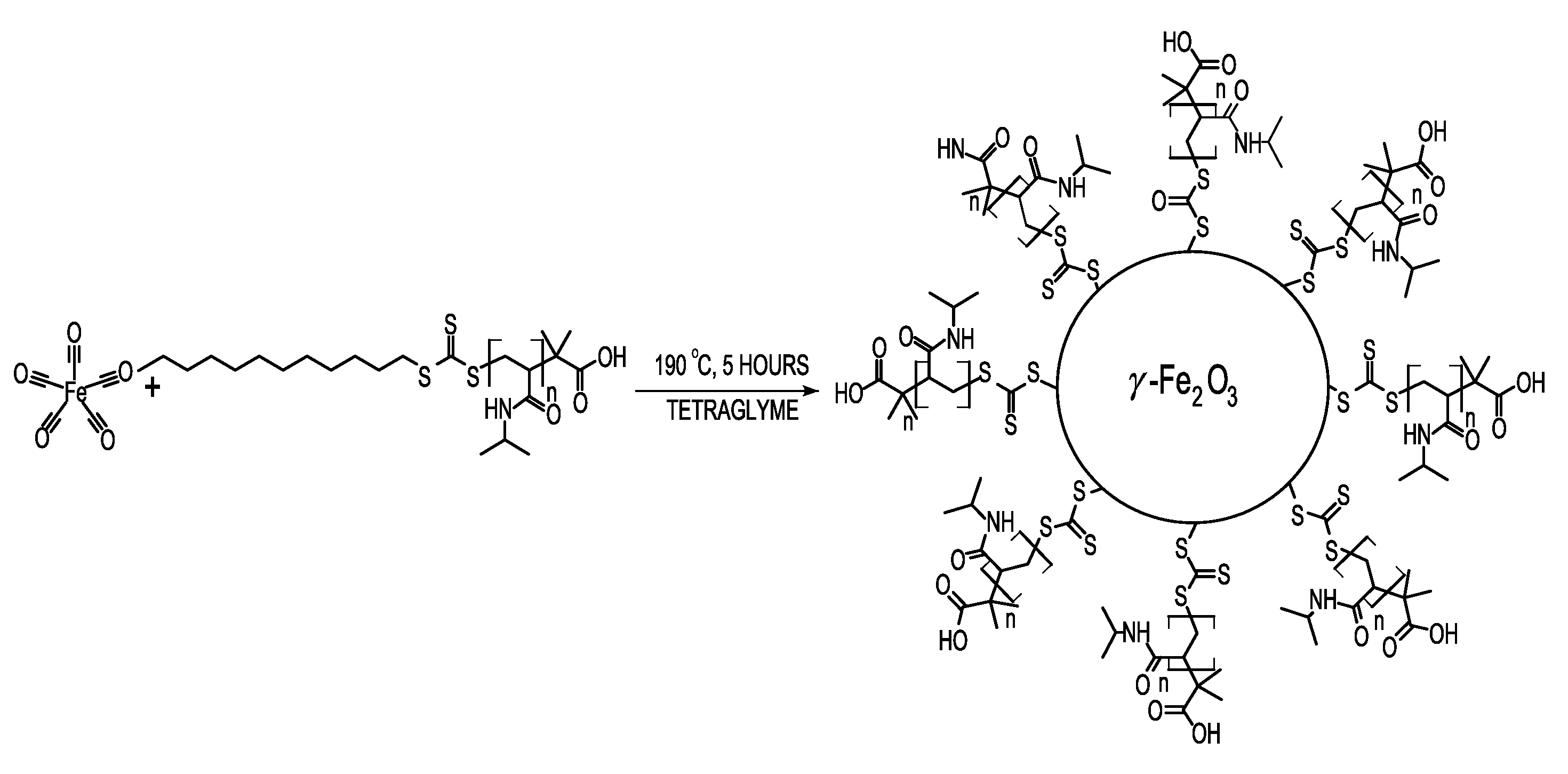
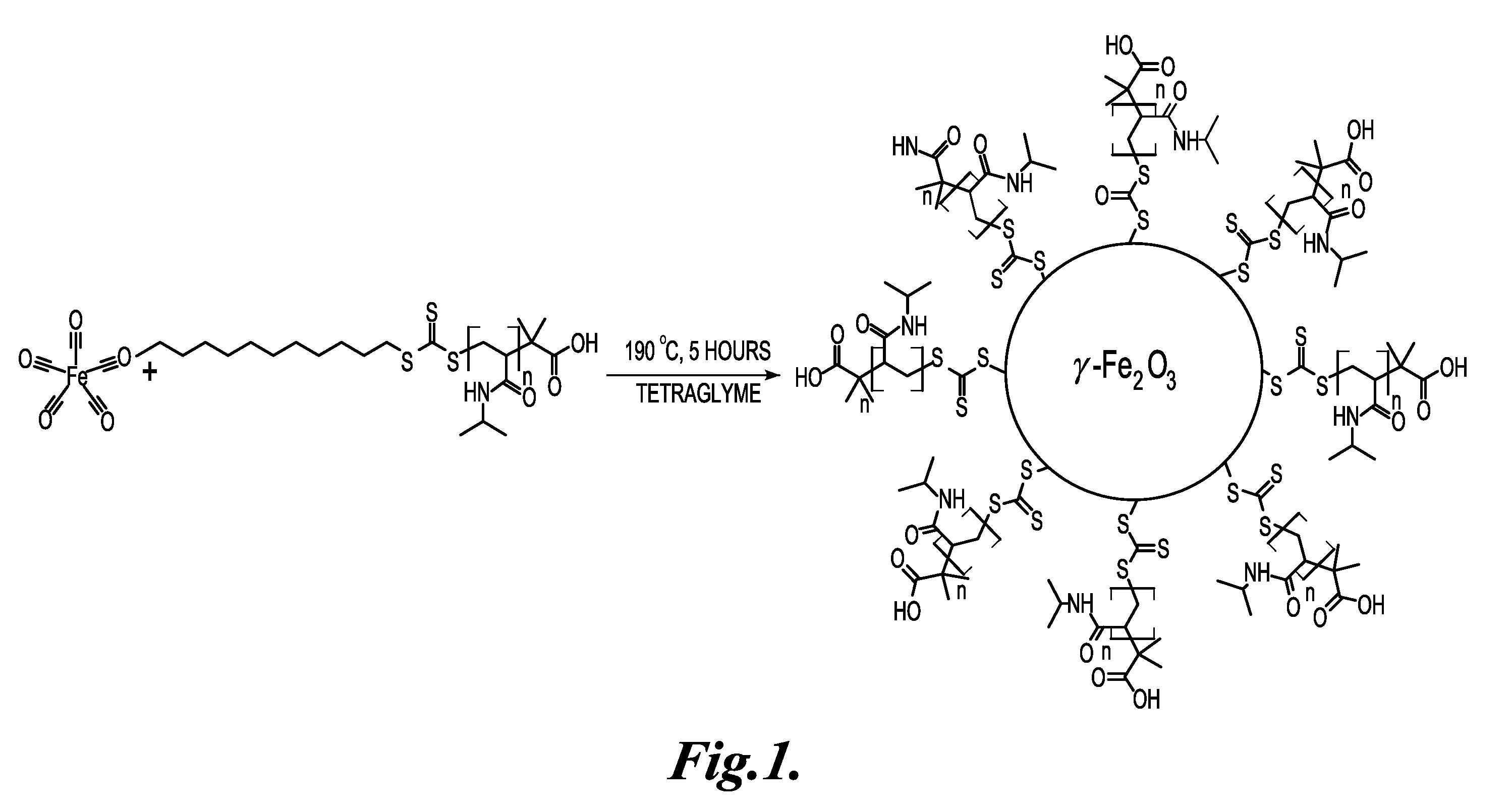
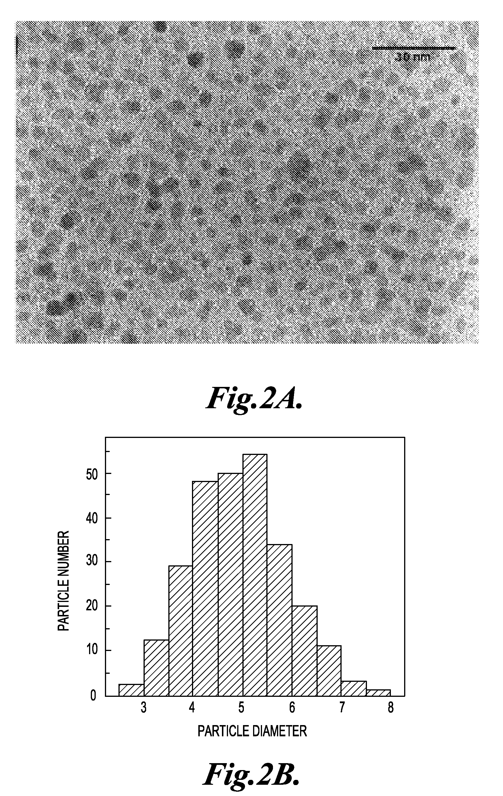
[0156]In this example, the preparation and characterization of representative temperature-responsive nanoparticles of the invention is described.

[0157]Materials. N-Isopropylacrylamide (NIPAAm) (Aldrich, 97%) was recrystallized from benzene / hexane 3:2 (v:v) and dried under vacuum prior to use. 2-dodecylsulfanylthiocarbonylsulfanyl-2-methyl propionic acid (DMP) is a gift from Noveon. Iron pentacarbonyl / Fe(CO)5 (Aldrich, 99.999%), 4,4′-Azobis(4-cyanovaleric acid) (Aldrich, 75+%), tetraethylene glycol dimethyl ether / tetraglyme (Aldrich, 99%), N-hydroxysuccinimide / NHS (Aldrich, 98%), methanol (EMD, 99.8%), hexane (EMD, 89.2%), tetrahydrofuran / THF (EMD, 99.99+%), p-dioxane (EMD, 99%), biotin (Aldrich), HABA / avidin reagent (Aldrich), EZ-Link® Biotin-LC-PEO-Amine and N,N′-dicyclohexylcarbodiimide / DCC (Pierce) was used without any purification.

[0158]Synthesis of PNIPAAm. Polymerization of PNIPAAm was p...

example 2

The Preparation of a Stimuli-Responsive Microfluidic Separation System

[0167]SU-8 Master and PDMS Device Fabrication. A silicon wafer was spin-coated with SU8-50 and baked at 95° C. for 1 h. The photoresist was exposed to UV light (Kaspar-Quintel model 2001 aligner) for 150 s through transparency masks. After exposure, the masters were baked at 95° C. for 10 min and developed with SU-8 developer (Microchem) for 15 min. The masters used in this study were 0.1 mm tall and 0.5 mm wide. Patterned masters and bare silicon wafers were passivated by 10 minute exposure to silane under vacuum. PDMS prepolymer was prepared by mixing PDMS base with a curing agent in a 10:1 ratio by weight and degassing the mixture under vacuum. To fabricate fluid channels, the mixture was cast against the pattered silicon master. To fabricate the lower surface, the mixture was cast over a bare silicon wafer. In both cases the samples were cured at 60° C. for 3 h. A piece of silicone tubing was embedded into the...


PUM

PropertyMeasurementUnit
Diameteraaaaaaaaaa
Diameteraaaaaaaaaa
Diameteraaaaaaaaaa

Abstract

Stimuli-responsive magnetic nanoparticles, methods of making the nanoparticles, and methods of using the nanoparticles.

Description

STATEMENT OF GOVERNMENT LICENSE RIGHTS[0001]This invention was made with government support under Government Contract No. 5 R0I EB 000252-09 awarded by the National Institutes of Health, National Institute of Biomedical Imaging and Bioengineering. The Government has certain rights in the invention.FIELD OF THE INVENTION[0002]The present invention relates to stimuli-responsive magnetic nanoparticles, methods for making the nanoparticles, and methods for using the nanoparticles.BACKGROUND OF THE INVENTION[0003]There has been considerable recent interest in the development of magnetic nanoparticle (mNP) technologies for diagnostic and imaging applications. Compared to larger magnetic particles, the smaller nanoparticles (NPs) display potential advantages in their diffusive and superparamagnetic properties. Magnetophoretic mobility, μm, is defined as the acceleration of an object in the presence of a magnetic field, which determines the ability to control the object's movement within a ...

Claims


Application Information

Patent Timeline
IPC IPC(8): G01N33/20B01J19/00H01F1/00C01G49/02
CPCB82Y25/00H01F1/0054G01N33/54326C01G49/02
Inventor STAYTON, PATRICK S.HOFFMAN, ALLAN S.LAI, JR-IUANHOFFMAN, JOHNEBARA, MITSUHIRO
Owner UNIV OF WASHINGTON
Learn More