Equipment for Non-Contact Temperature Measurement of Samples of Materials Arranged Under Vacuum

a vacuum chamber and temperature measurement technology, applied in the direction of heat measurement, optical radiation measurement, instruments, etc., can solve the problems of distorting measurement, measurement methods that did not produce satisfactory, and still cannot be fully satisfactory, so as to achieve high reflective power, increase the degree of freedom, and the effect of high quality

Inactive Publication Date: 2008-09-18
EUROPEAN SPACE AGENCY
View PDF10 Cites 16 Cited by
  • Summary
  • Abstract
  • Description
  • Claims
  • Application Information

AI Technical Summary

Benefits of technology

[0031]In a preferred embodiment of the invention, the scanning device includes a mirror, with high reflective power for infrared wave lengths, and a component that rotates the mirror according to two orthogonal axes. The mirror is positioned on the optical path between the pyrometer and the samples, ideally such that the pyrometer's focal point be on the surface of samples. This arrangement enables a focussing on the surface of a determined material sample, on a zone of small surface. This arrangement further enables the sequential scanning, not only of a plurality of samples of materials, advantageously of materials exhibiting different emissive coefficients. It also enables the creation of a detailed chart and specifies the full surface of each of the samples of material to be tested. Lastly, it should be noted that a two-dimensional surface map of temperatures does apply for samples surface, but also apply for the surfaces of a spaceship or of various components, for example, during a thermal balance test.
[0032]In a still further preferred embodiment, the scanning device further comprises a component enabling a translation movement following the three axes of an orthonormal trihedral, one comprised in a plane that shall be referred to arbitrarily as horizontal, the other in a vertical plane, thereby increasing its degree of freedom.
[0033]In a still further preferred embodiment, when the samples of materials to be tested are made of film of slight thickness, the side of supports in contact with these samples presents a convex curve surface, such that the films can be pressed firmly against the support. It follows that a thermal contact of very high quality can be obtained. With this advantageous arrangement, the risk of samples detaching, as noted with plane supports, is thereby avoided.

Problems solved by technology

The experiment showed that these measurement methods did not produce satisfactory results.
Nevertheless, the results obtained here were still not fully satisfactory for the following reasons:the surfaces of the samples of materials cannot be mapped at different thermal emissive coefficients during a simple camera scan;individual focussing on different samples of materials cannot be obtained; anda significant retroreflection of the radiation produced by the UV source and its transmission window was noted, thereby distorting the measurement.
Particularly, they do not provide a solution for all evident requirements, in particular that of the high precision measurement of the temperature reached by a plurality of samples of different materials, particularly made up of films of very slight thickness, arranged in a vacuum chamber, nor do they enable the creation of the chart of temperatures for their surface.
Nevertheless, it has been noted that this arrangement led to a procedure necessitating a high quantity of manual operations which, furthermore, are long and complex.
The methods in prior art also do not enable the elimination, or at least the very significant reduction, of the unwanted influence of the environment.

Method used


Image

  • Equipment for Non-Contact Temperature Measurement of Samples of Materials Arranged Under Vacuum
  • Equipment for Non-Contact Temperature Measurement of Samples of Materials Arranged Under Vacuum
  • Equipment for Non-Contact Temperature Measurement of Samples of Materials Arranged Under Vacuum

Examples


Embodiment Construction

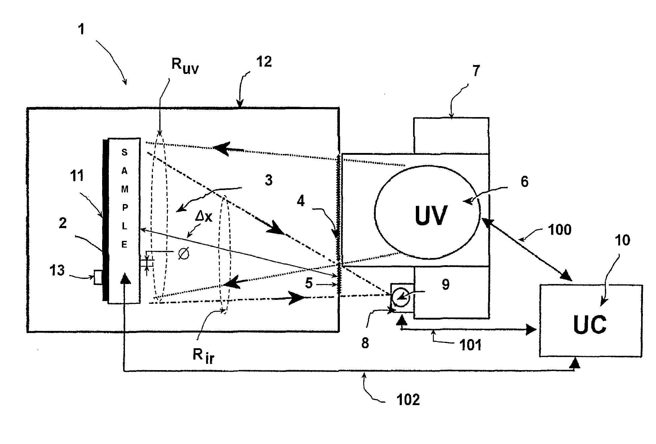
[0052]The following shall focus, without restricting the scope of the present invention in any way, on the context of the preferred application of the invention, unless specified to the contrary, i.e., the case of an equipment for measurement of samples of materials, arranged in a chamber having a high vacuum and subjected to environmental tests simulating a space mission during which these samples of materials will be subjected to high temperatures. More specifically, the case of samples of materials made up of films of very slight thickness, foil or similar, shall be considered.

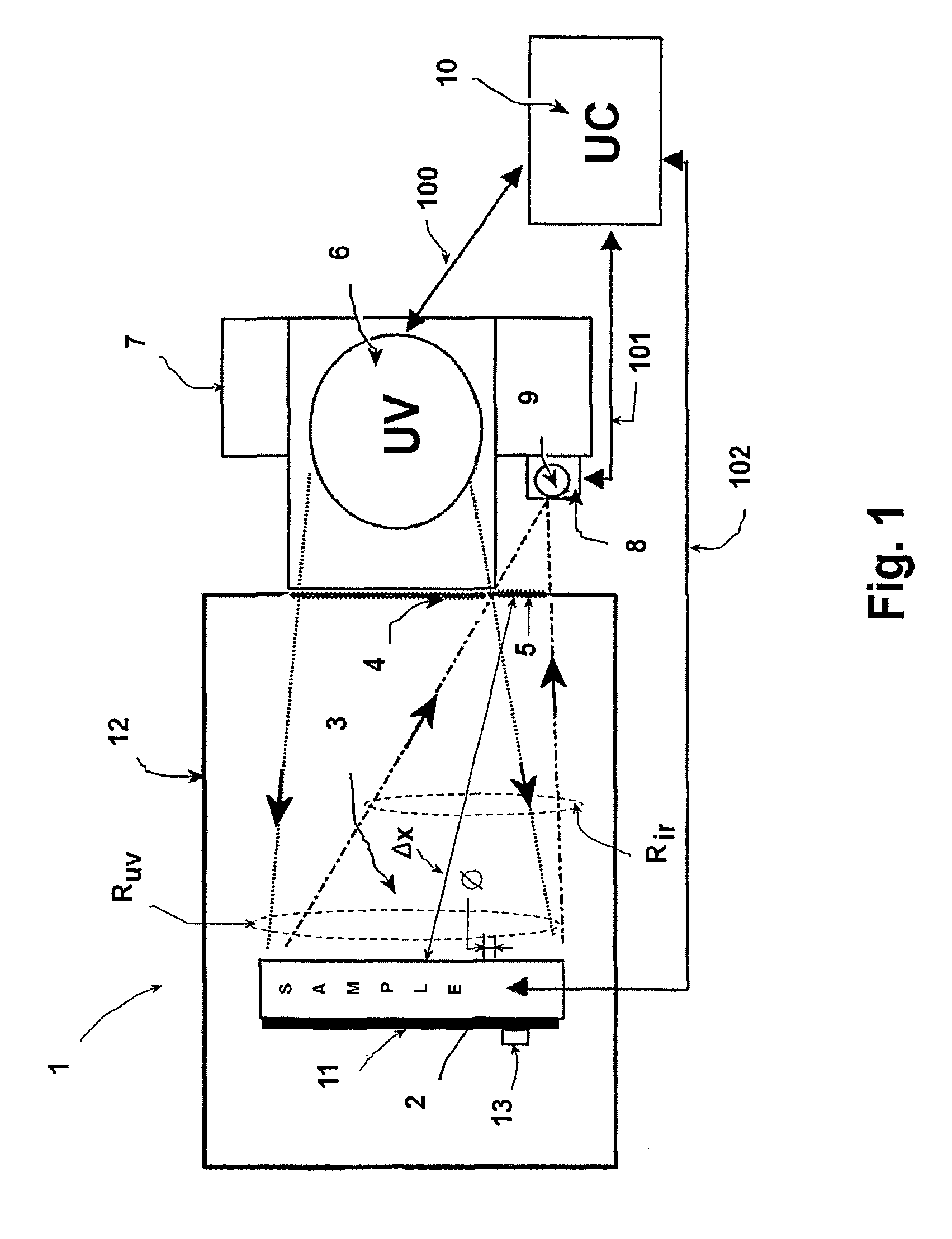
[0053]An embodiment example of an equipment for non-contact measurement will now be described according to a preferred embodiment of the invention with reference to FIGS. 1 to 4. In these figures, the common elements have the same references and will not be described again unless necessary.

[0054]FIG. 1 illustrates schematically, as a whole, a configuration example for an equipment for non-contact measuremen...


PUM


Abstract

The invention concerns an equipment for non-contact temperature measurement (1) of samples of materials (2) arranged in a vacuum chamber (12). A UV lamp (6) illuminates the samples (2) through a window (4), so as to subject them to a predetermined thermal cycle and to perform an environmental test, in particular for materials designed for space missions. An external pyrometer measures the temperature of the samples (2) through a window (6). It is associated with a scanning module (9) including a mobile mirror, with two axes of rotation and three orthogonal axes of translation, arranged on the optical path of the infrared radiation (Rir) so as to obtain a two-dimensional scanning of each sample (2) by means of a measuring spot focused on the surface of the samples. In a preferred embodiment, the samples are of slight thickness and locked pressed against a convex support The whole assembly is monitored by an automatic data processing system with recorded programme (10).

Description

RELATED APPLICATIONS[0001]This application is a §371 from PCT / FR2006 / 001305 filed Jun. 7, 2006, which claims priority from FR 05 51563 filed Jun. 9, 2005, each of which is herein incorporated by reference in its entirety.FIELD OF THE INVENTION[0002]The invention concerns an equipment for non-contact temperature measurement of samples arranged in a vacuum chamber.[0003]It has particular application, although non-exhaustive, for testing materials destined for space missions, and even more particularly to space missions inside the solar system or similar. The materials are then subjected to temperatures significantly higher than those recorded for earth-orbiting space missions. As non-exhaustive examples, the “BepiColombo” and “Venus Express” missions can be quoted.[0004]To fix ideas, the following shall focus on the context of the preferred application of the invention, without restricting its scope in any way. In this context of application, it is evident that temperature is a signif...

Claims


Application Information

Patent Timeline
Patent Type & Authority Applications(United States)
IPC IPC(8): G01J5/00
CPCG01N25/72G01K13/00
Inventor SEMPRIMOSCHNIG, CHRISTOPHVAN EESBEEK, MARCHELTZEL, STAN
Owner EUROPEAN SPACE AGENCY
Why Eureka
Try Eureka