
Recording apparatus and liquid ejecting apparatus

a technology of liquid ejecting apparatus and recording apparatus, which is applied in the direction of measurement apparatus components, instruments, printing, etc., can solve the problems of troublesome operation of recording apparatus, increased cost of product including various types of coat layers, etc., and achieves the suppression of stripping of layers, high quality, and improved recording operation.

Inactive Publication Date: 2008-09-18
SEIKO EPSON CORP
View PDF6 Cites 25 Cited by
  • Summary
  • Abstract
  • Description
  • Claims
  • Application Information

AI Technical Summary

Benefits of technology

[0014]In the recording apparatus, the carriage may be moved in a direction in which the coat head precedes the recording head, when the undercoat layer is formed, and may be moved in a direction in which the recording head precedes the coat head, when the overcoat layer is formed. Accordingly, since the image and the coat layer can be continuously formed by moving the carriage relative to the recording medium one time, the throughput of the recording operation can be improved.
[0015]In the recording apparatus, when the overcoat layer is formed, the irradiation amount of the ultraviolet rays irradiated from the ultraviolet ray irradiation unit to the coat ink may be lower than that when the undercoat layer is formed. Accordingly, since the surface of the overcoat layer formed on an uppermost surface of the image smoothens, it is possible to form an image with high quality.
[0016]In the recording apparatus, a plurality of ultraviolet ray irradiation units may be arranged at the downstream side of the rotation direction of the support drum, with respect to the recording head and the coat head. Accordingly, with respect to the recording head and the coat head, it is possible to form the ultraviolet ray irradiation unit for irradiating the ultraviolet rays under the individual conditions suitable for the inks ejected from the heads. Thus, it is possible to suppress the stripping of the layers due to excessive curing, sufficiently cure the inks, and form an image with high quality.
[0017]In the recording apparatus, the coat ink ejected from the coat head may be any one of a white ink and a transparent ink. Accordingly, the white coat layer is formed on the surface of a transparent or colored recording medium or the surface of the image formed on a transparent recording medium so as to improve the color of the image. In addition, since the surface of the image formed on the recording medium is covered with the transparent coat layer, the image can be protected and the surface of the image can smoothen.
[0018]According to a second aspect of the invention, there is provided a liquid ejecting apparatus including: a support drum which rotates while supporting a recording medium on a support surface thereof; a guide shaft which is spaced apart from the support surface by a predetermined distance and extends in parallel to a direction perpendicular to a rotation direction of the support drum; a carriage which is guided by the guide shaft and is reciprocally moved along the support surface; a liquid ejecting head which is transported by the carriage and ejects liquid including an ultraviolet curing component toward the recording medium supported by the support surface; a coat head which is transported by the carriage, is provided at least one of a front side and a back side of the liquid ejecting head in a reciprocal movement direction of the carriage, and ejects an ultraviolet curing coat material forming at least one of an undercoat layer formed on the recording medium and an overcoat layer superimposed on an ink layer adhered to a surface of the recording medium; and an ultraviolet ray irradiation unit which irradiates ultraviolet rays to the liquid and the coat material which are ejected from the liquid ejecting head and the coat head and are adhered to the recording medium; and wherein, whenever the support drum is rotated at least one revolution, the carriage is moved along the guide shaft so as to form a pattern formed by the liquid and the coat material over the overall surface of the recording medium supported by the support drum. Accordingly, even in the liquid ejecting apparatus, the above-described effect can be obtained.

Problems solved by technology

Since the printing sequences of the case of forming the undercoat layer and the case of forming the overcoat layer or the back coat layer are inverse, the operation of the recording apparatus is troublesome.
Accordingly, the cost of a product including various types of coat layers is increased.

Method used


Image

  • Recording apparatus and liquid ejecting apparatus
  • Recording apparatus and liquid ejecting apparatus
  • Recording apparatus and liquid ejecting apparatus

Examples


embodiment

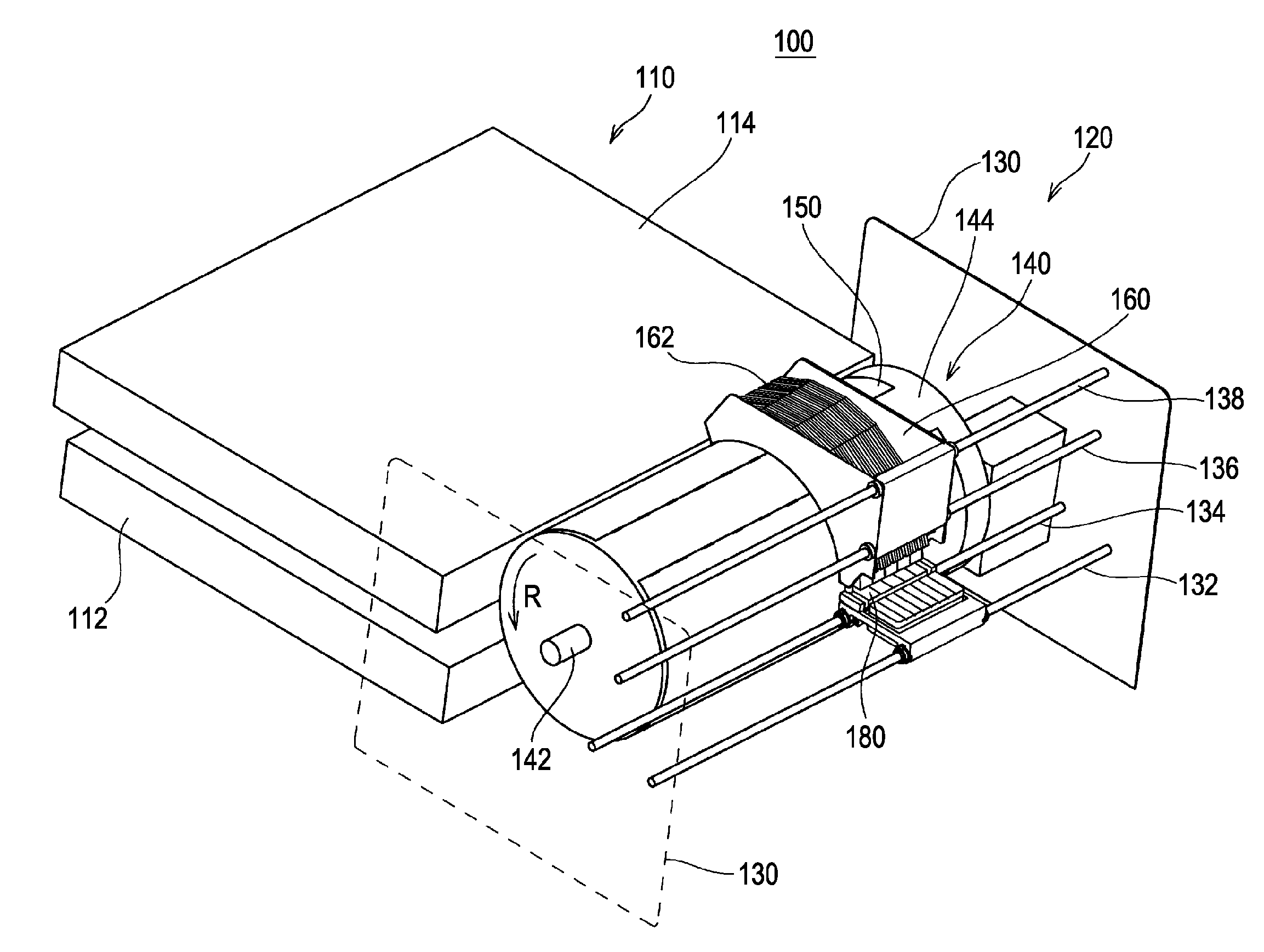
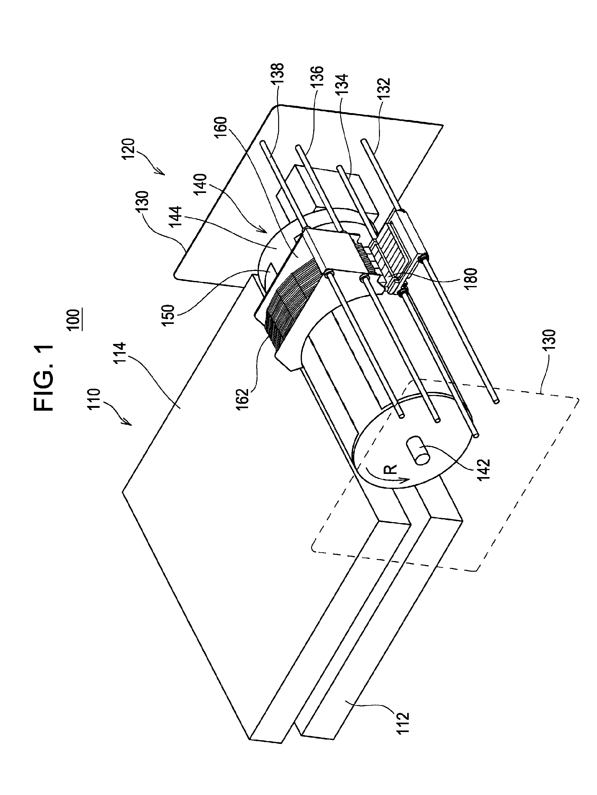
[0033]FIG. 1 is a schematic view the overall structure of an ink jet recording apparatus 100 according to an embodiment of the invention. As shown in FIG. 1, the ink jet recording apparatus includes a recording unit 120 interposed between a pair of erected frames 130, which face each other, and a feeding / ejecting unit 110 including a feeding unit 112 and an ejecting unit 114.

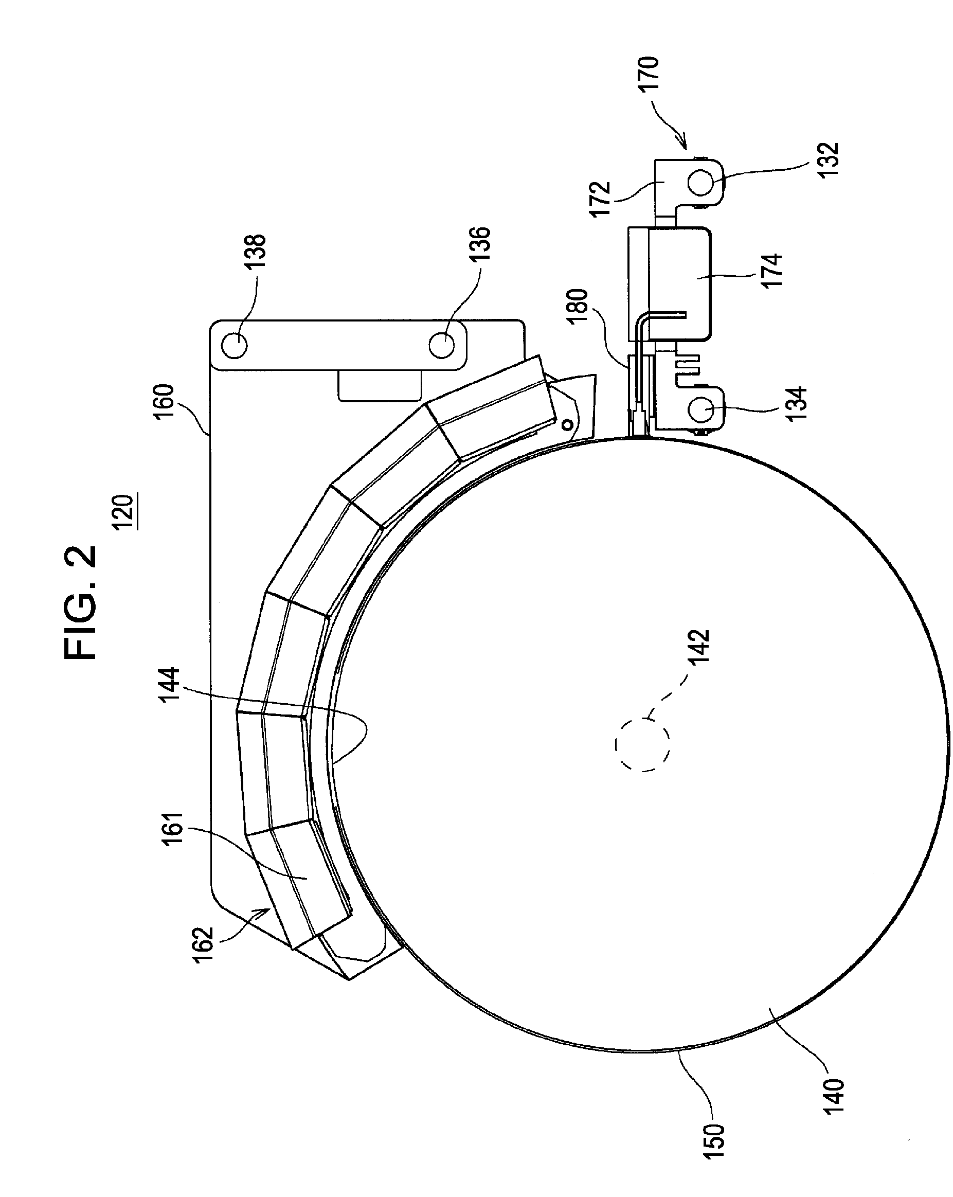
[0034]The recording unit 120 includes a support drum 140 and guide shafts 132, 134, 136 and 138, all of which are supported between the pair of parallel frames 130. The support drum 140 is rotated in a direction denoted by an arrow R shown in the drawing in a state in which a rotation shaft 142 is pivoted from the frames 130 and a recording sheet 150 is maintained on a support surface 144. A member for rotating the support drum 140 is not shown.

[0035]Meanwhile, among two pairs of parallel guide shafts 132, 134, 136 and 138, a pair of guide shafts 132 and 134 passes through a recording unit carriage 170 and suppo...


PUM


Abstract

A recording apparatus includes a support drum which rotates while supporting a recording medium on a support surface thereof. A guide shaft of the recording apparatus is spaced apart from the support surface by a predetermined distance and extends in parallel to a direction perpendicular to a rotation direction of the support drum. A carriage which is guided by the guide shaft is reciprocally moved along the support surface. A recording head mounted on the carriage ejects an ultraviolet curing ink toward the recording medium. An ultraviolet ray irradiation unit irradiates ultraviolet rays to the ultraviolet curing inks which are ejected from the recording head. In operation, the carriage is moved along the guide shaft so as to form an image formed by the ultraviolet curing ink and a coat ink over the overall surface of the recording medium supported by the support drum.

Description

BACKGROUND[0001]1. Technical Field[0002]The present invention relates to a recording apparatus and a liquid ejecting apparatus and more particularly to a recording apparatus and a liquid ejecting apparatus using an ultraviolet curing ink.[0003]2. Related Art[0004]There is provided a recording apparatus or a liquid ejecting apparatus for forming an image or a pattern on a recording medium using an ultraviolet curing ink. The ultraviolet curing ink has preferred characteristics that the ultraviolet curing ink is slowly cured before ultraviolet rays are irradiated and is rapidly cured when the ultraviolet rays are irradiated, as a print ink. Since a solvent is not volatilized at the time of curing, an environment load is small.[0005]The ultraviolet curing ink has excellent characteristics that an adhesion property is high with respect to various recoding mediums due to composition of vehicle, the ink becomes chemically stable after curing, an adhesion property, chemical resistance, wea...

Claims


Application Information

Patent Timeline
Patent Type & Authority Applications(United States)
IPC IPC(8): B41J2/01
CPCB41J2/15B41J2202/20B41J11/002B41J11/0015B41J11/00214
Inventor KUMAGAI, TOSHIO
Owner SEIKO EPSON CORP
Learn More