Refrigerating Apparatus

a technology of refrigerating equipment and compressor, which is applied in lighting and heating equipment, program control, instruments, etc., can solve the problem of not placing the supercool unit in operation, and achieve the effect of enhancing cooling capacity, reducing the number of operational man-hours, and reducing the power consumption of the compressor

Inactive Publication Date: 2008-09-25
DAIKIN IND LTD
View PDF5 Cites 25 Cited by
  • Summary
  • Abstract
  • Description
  • Claims
  • Application Information

AI Technical Summary

Benefits of technology

[0069]In accordance with the first problem solving means, the control means (240) reduces the power consumption of the pump mechanism (221) either based on the state of refrigerant of the refrigerant circuit (20) flowing through the supercool heat exchanger (210) or based on the state of cooling fluid of the cooling fluid circuit (220) and the temperature of outside air. This therefore makes it possible for the control means (240) to reduce the power consumption of a compressor such as the pump mechanism (221) without having to receive any signals indicative of the operating status of the refrigerant circuit (20). This reduces the power consumption of the cooling fluid circuit (220), thereby making it possible to control the overall power consumption of the refrigerating apparatus. This ensures that the refrigerating apparatus is able to operate within the contract demand.
[0070]In addition, even when the cooling fluid circuit (220) is additionally installed to an existing refrigerating apparatus, there is no need to arrange any new communication wiring for the transferring of signals between the refrigerant circuit (20) and the cooling fluid circuit (220). Accordingly, it becomes possible to reduce the number of operational man-hours required to attach the cooling fluid circuit (220) to the refrigerating apparatus. Further, it becomes possible to enhance the cooling capacity while preventing troubles (e.g. faulty wiring) caused by human errors from occurring during the installation work.
[0071]Furthermore, in accordance with the second problem solving means, it is arranged such that power consumption relating to the refrigerant circuit (20) is estimated based on the refrigerant state of the refrigerant circuit (20) and other parameter. This arrangement ensures that the amount of reduction in power consumption relating to the cooling fluid circuit (220) can be grasped. This ensures that the refrigerating apparatus is able to operate within the contract demand.
[0072]In addition, in accordance with the eleventh problem solving means, the heat absorption temperature or the evaporating temperature of cooling fluid in the supercool heat exchanger (210) is higher than the evaporating temperature of refrigerant in the utilization side heat exchanger (101, 111, 131). The difference between the high pressure and the low pressure of cooling fluid in front of and behind the pump mechanism (221) of the cooling fluid circuit (220) is smaller than the difference between the high pressure and the low pressure of the refrigeration cycle in the refrigerant circuit (20). And in the refrigerating apparatus of the present invention, the amount of refrigerant circulation is not increased in the refrigerant circuit (20) having a greater high-low pressure difference, but the power consumption (the amount of work) of the pump mechanism (221) et cetera is increased so that the flow rate of cooling fluid is increased in the cooling fluid circuit (220) having a smaller high-low pressure difference, whereby the power consumption of the cooling fluid circuit (220) is preferentially increased. To sum up, the amount of work of the pump mechanism (221) et cetera whose load is originally small is preferentially increased to thereby cope with the increase of the load. For this reason, it becomes possible to control the increase in input power necessary for dealing with the increase in load, thereby making it possible to prevent the drop in coefficient of performance. As a result the amount of increase in overall power consumption of the refrigerating apparatus can be controlled.
[0073]Furthermore, in accordance with the twelfth problem solving means, the target value is set based on the ambient condition of the supercool heat exchanger (210), e.g. the temperature of outside air, the flow rate of refrigerant et cetera, so that the power consumption of the cooling fluid circuit (220) is preferentially increased if there is an increase in load. Accordingly, it becomes possible to ensure that the power consumption of the cooling fluid circuit (220) is preferentially increased depending on the load state.
[0074]Besides, since the load state of the refrigerating apparatus is estimated using only the information obtained within the cooling fluid circuit (220), this eliminates the need for providing communication wiring for the transferring of signals between the refrigerant circuit (20) and the cooling fluid circuit (220).

Problems solved by technology

In addition, the supercool unit is not placed in operation when the refrigerating apparatus operates as a heat pump, e.g. when the air conditioning system is in the heating operating mode.

Method used


Image

  • Refrigerating Apparatus
  • Refrigerating Apparatus
  • Refrigerating Apparatus

Examples


first embodiment

of the Invention

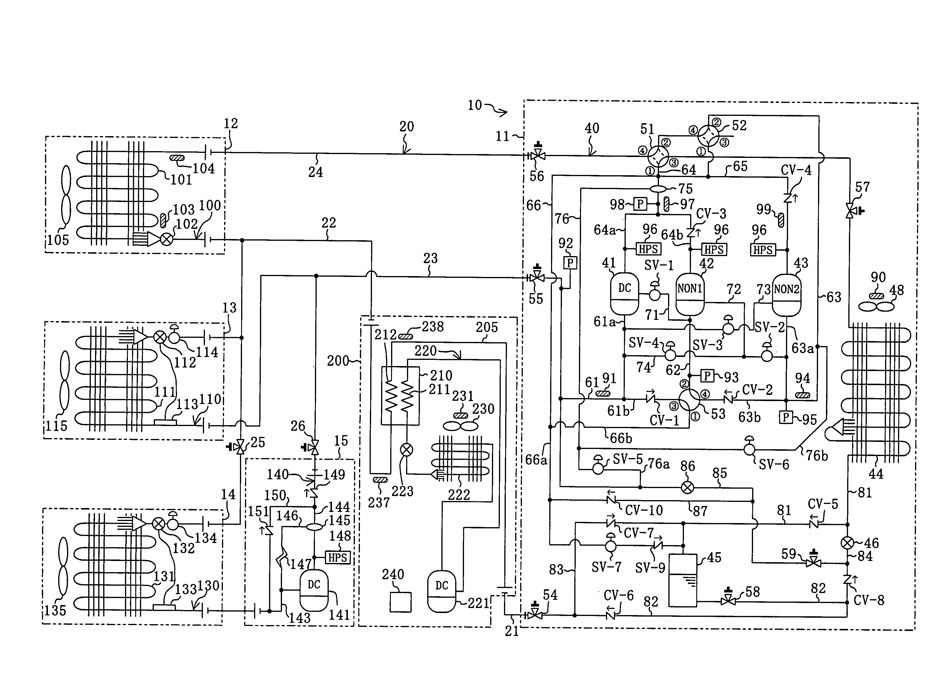
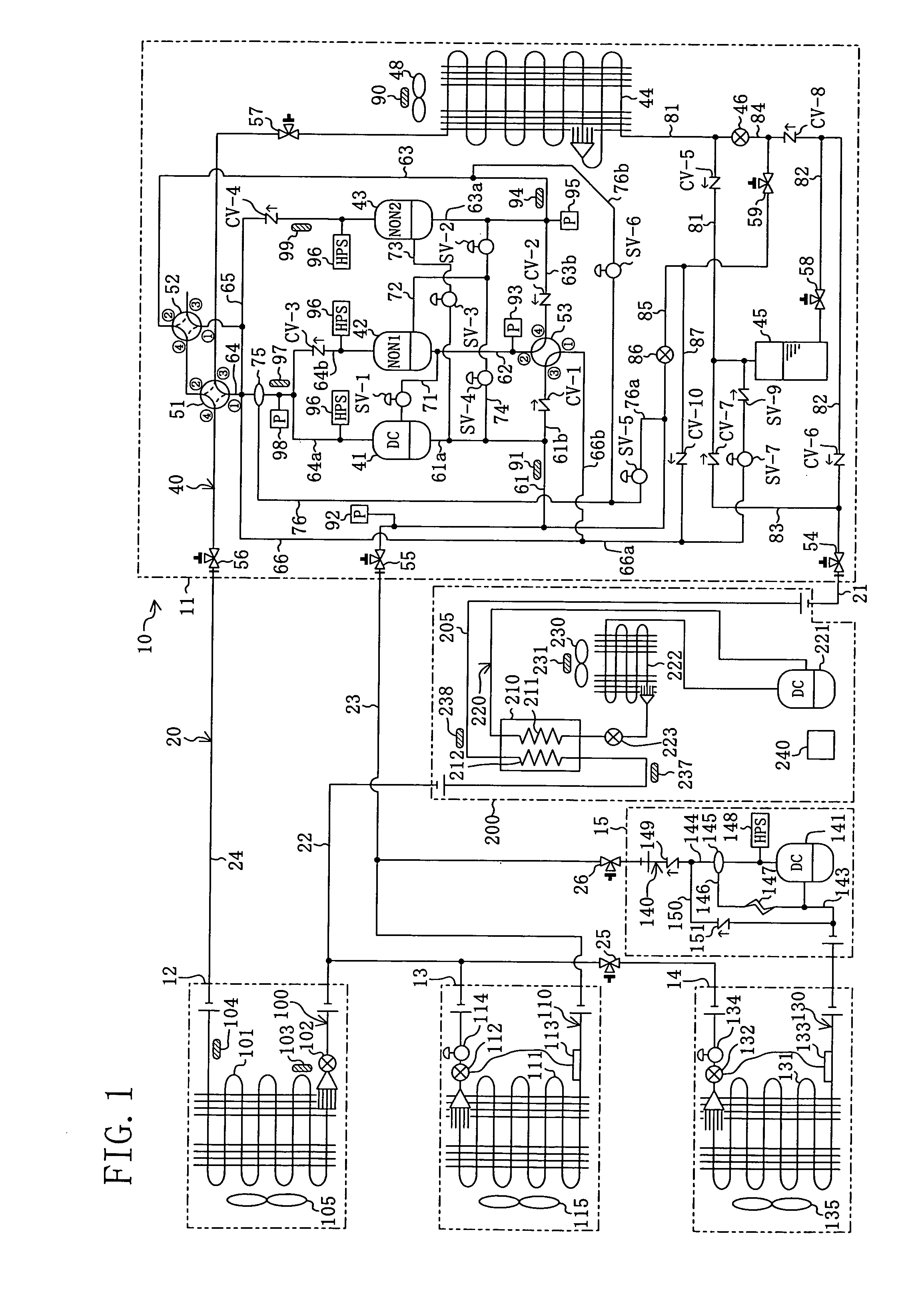
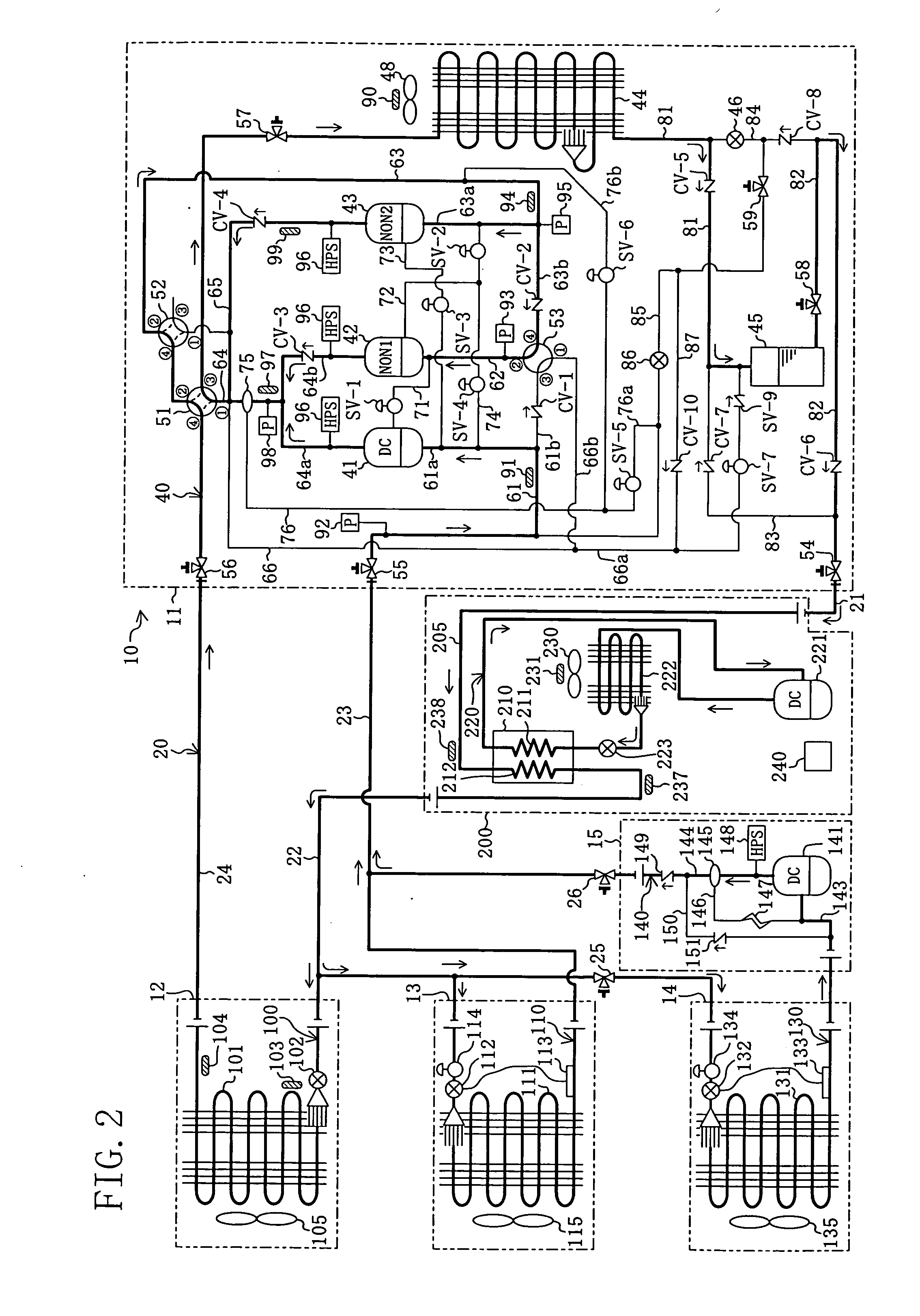
[0085]A first embodiment of a refrigerating apparatus (10) according to the present invention is intended for installation in a convenience store or the like and provides air conditioning of the inside of the store and cooling of the inside of showcases. As shown in FIG. 1, the refrigerating apparatus (10) is provided with a supercool refrigerant circuit (220) which includes a supercool heat exchanger (210) and a supercool compressor (221) and through which supercool refrigerant as cooling fluid flows, and a refrigerant circuit (20) which includes utilization side heat exchangers (101, 111, 131) and heat source side compressors (41, 42, 43). The refrigerating apparatus (10) is configured such that refrigerant flowing through the refrigerant circuit (20) is supercooled through the supercool heat exchanger (210) of the supercool refrigerant circuit (220). In other words, the supercool refrigerant circuit (220) constitutes a cooling fluid circuit in accordance with the ...

second embodiment

of the Invention

[0182]Instead of reducing the power consumption of the supercool compressor (221) by directly stopping the supercool compressor (221) as in the first embodiment, the operating frequency of the outdoor fan (230) of the supercool outdoor heat exchanger (222) is increased to thereby reduce the power consumption of the supercool compressor (221) in the refrigerating apparatus (10) of the second embodiment. In other words, in the present embodiment, the operating frequency of the supercool compressor (221) is held constant.

[0183]More specifically, when the degree of supercooling of the refrigerant of the refrigerant circuit (20) is large, it is estimated that power consumption relating to the refrigerant circuit (20) is small, and the operating frequency of the outdoor fan (230) is not changed by the controller (240). On the other hand, when the degree of supercooling is small, it is estimated that power consumption relating to the refrigerant circuit (20) is large, and t...

third embodiment

of the Invention

[0185]Unlike the first embodiment in which the cooling fluid circuit is formed by a refrigerant circuit through which supercool refrigerant is circulated, the cooling fluid circuit in the refrigerating apparatus (10) of the third embodiment is formed by a cooling water circuit through which cooling water flows, which is not shown diagrammatically. More specifically, this cooling water circuit includes, in addition to the supercool heat exchanger (210), a pump, wherein cooling water held in a cooling tower is delivered by the pump to the supercool heat exchanger (210). Then, in the supercool heat exchanger (210), the cooling water exchanges heat with refrigerant in the refrigerant path (205), as a result of which the refrigerant is cooled. To sum up, in the cooling fluid circuit of the present embodiment, cooling water flows as a cooling fluid.

[0186]In this case, the controller (240) regulates the operating capacity of the pump based on the degree of supercooling of t...


PUM


Abstract

An outside air temperature sensor (231) for detecting the temperature of outside air, and a control means (240) for controlling the operating capacity of a supercool compressor (221) are provided. The control means (240) controls the operation of the supercool compressor (221) based on the state of refrigerant of a refrigerant circuit (20) flowing through a supercool heat exchanger (210) and the temperature of outside air detected by the outside air temperature sensor (231).

Description

TECHNICAL FIELD[0001]The present invention relates to a refrigerating apparatus including a supercool unit adapted to supercool refrigerant which is delivered from one equipment on the heat source side to another on the utilization side.BACKGROUND ART[0002]A conventional type of refrigerating apparatus has been known in the art which includes a first refrigerant circuit having a supercool heat exchanger, and a second refrigerant circuit having a utilization side heat exchanger and a heat source side compressor. In an attempt to enhance the cooling capacity of the refrigerating apparatus a second refrigerant in the second refrigerant circuit is supercooled through the supercool heat exchanger. One such refrigerating apparatus is disclosed in, for example, JP H10-185333A.[0003]This refrigerating apparatus which is in the form of an air conditioning system is provided with an outdoor unit, an indoor unit, and a supercool unit. More specifically, the supercool unit is disposed along a l...

Claims


Application Information

Patent Timeline
Patent Type & Authority Applications(United States)
IPC IPC(8): F25B41/00F25B1/00F25B39/02G05B19/00
CPCF25B1/10F25B7/00F25B13/00F25B2313/007F25B2313/02331Y02B30/741F25B2400/22F25B2400/23F25B2600/021F25B2700/2103F25B2700/2106F25B2400/0751Y02B30/70F25B1/00
Inventor TAKEGAMI, MASAAKITANIMOTO, KENJISAKAE, SATORUSHINOHARA, IWAOKONDO, AZUMA
Owner DAIKIN IND LTD
Why Eureka
Try Eureka