Vortex structure for high throughput continuous flow separation

a vortex structure and high throughput technology, applied in the direction of separation process, multi-stage water/sewage treatment, instruments, etc., can solve the problems of low yield and laborious recovery of captured pathogens from these membranes, and the device is not miniaturized

Inactive Publication Date: 2008-09-25
PALO ALTO RES CENT INC
View PDF23 Cites 23 Cited by
  • Summary
  • Abstract
  • Description
  • Claims
  • Application Information

AI Technical Summary

Benefits of technology

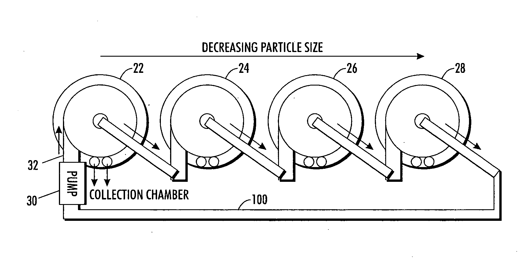
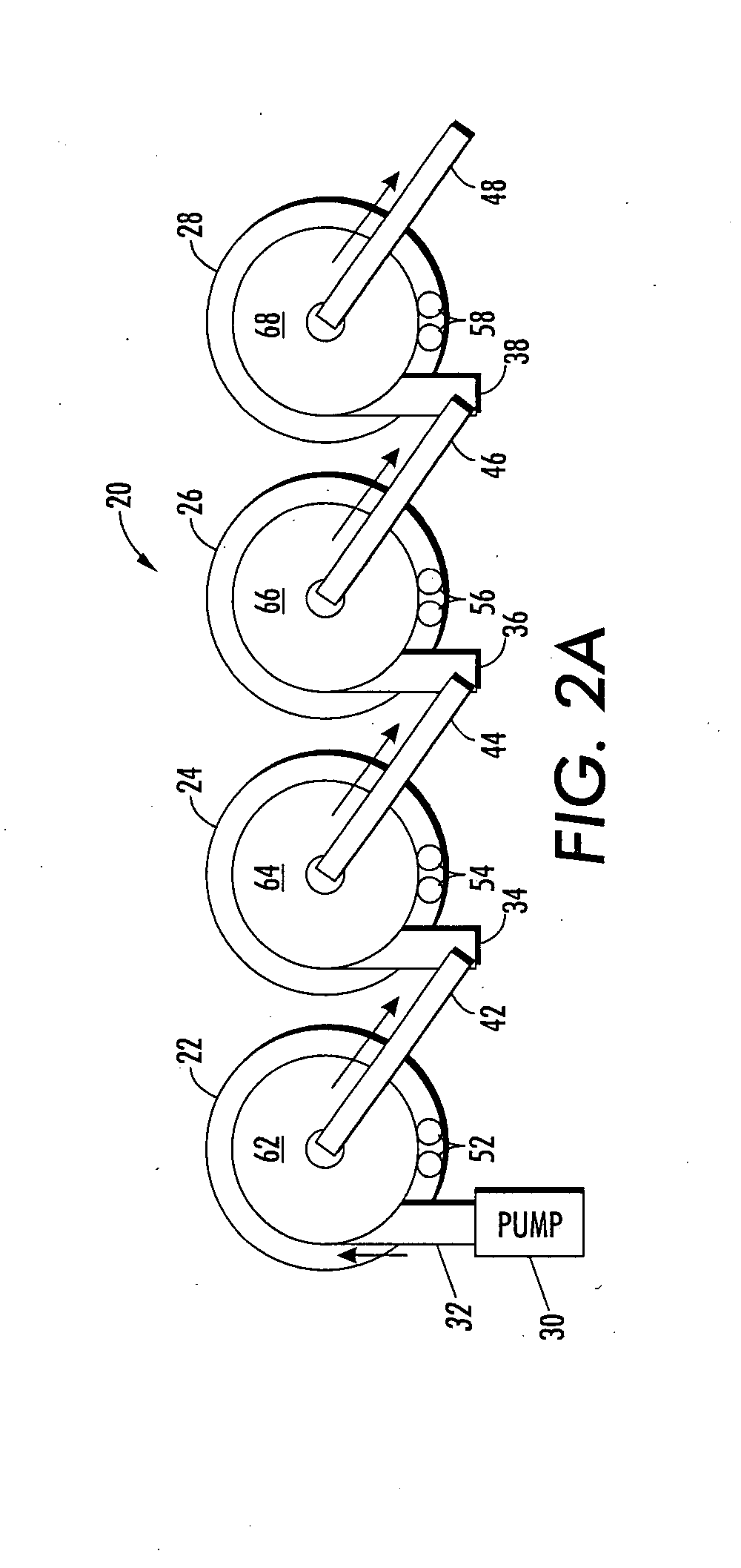
[0020]In another aspect of the presently described embodiments, a system comprises a system inlet for receiving the fluid and a plurality of devices cascaded to selectively process particles of varying size, each device comprising an inlet to receive the fluid, a chamber to capture particles in a selected size range by maintaining a vortex flow of the fluid in the chamber, and an outlet to expel the fluid from the chamber.

Problems solved by technology

However, those devices are not miniaturized and include an inner porous vertical wall.
Also, these prior systems rely on gravity for sedimentation and can therefore only separate out particles with sedimentation times shorter than the residence time of the particles within the structures.
In particular, the Tri-Service Standard for anthrax spores is 100 cfus / L, which poses a significant challenge in logistics, time, and concentration factor.
The biggest challenge to this method and to all these vendors is the low yield and laborious recovery of captured pathogens from these membranes.

Method used


Image

  • Vortex structure for high throughput continuous flow separation
  • Vortex structure for high throughput continuous flow separation
  • Vortex structure for high throughput continuous flow separation

Examples


example conditions

[0044

[0045]radius of the chamber (R)=0.0005 m

[0046]fluid velocity (v)=0.2 m / s

[0047]fluid density (ρ)=1050 kg / m3

[0048]chamber pressure (P)=70 Pa

[0049]Centrifugal Force

[0050]Fc=Mv2 / R=4 / 3πr3pv2 / R=107πr3p(m / s2)=105πr3(kg / m2s2)

[0051]Pressure-Driven Force

[0052]FP=Pπr2=70πr2Pa=70πr2 (kg / ms2)

[0053]So, if the radius of the particle (r)=1.5×10⁻⁶ m,

[0054]Fc=3.4πr×10−13(kgm / s2) and

[0055]FP=1.6 π×10−10(kgm / s2)

[0056]This illustrates, in at least this example, a difference between the centrifugal force Fc and pressure-driven force FP of three orders of magnitude. Thus, although the values may vary depending on the conditions experienced and implemented, these forces can be advantageously used to separate or concentrate particles.

[0057]Other observations with respect to the vortex characteristics include, but are not limited to, the following. First, it is advantageous to achieve a minimum fluid velocity to maintain the vortex flow in the system. In one form, this fluid velocity is 0.1 m / s for a c...


PUM

PropertyMeasurementUnit
sizesaaaaaaaaaa
radiusaaaaaaaaaa
radiusaaaaaaaaaa

Abstract

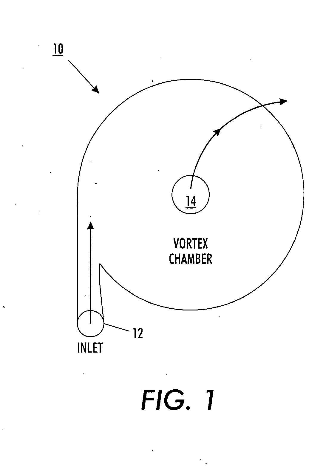
A system to facilitate separation and concentration of particles based on centrifugal force on suspended particles, including biological matter, which are made to flow in a vortex structure is provided. The centrifugal force urges larger particles to collect along outer portions of the vortex flow. Conversely, within a vortex structure, a radial hydrodynamic pressure drop is also amplified to urge smaller particles toward inner portions of the vortex flow. This force created by the pressure can reach magnitudes that encourage a sharp cut-off and improved resolution discrimination between particle sizes. Thus, separated streams of particles can be collected with both increased concentration and purification.

Description

CROSS REFERENCE TO RELATED PATENTS AND APPLICATIONS[0001]This application is related to U.S. application Ser. No. 11 / 606,458, entitled “Serpentine Structures for Continuous Flow Particle Separations,” filed Nov. 30, 2006 by Lean, et al. and U.S. application Ser. No. 11 / 606,460, entitled “Particle Separation and Concentration System”, filed Nov. 30, 2006 by Lean et al. which are incorporated herein by reference in their entirety.BACKGROUND[0002]Three U.S. patents describe macro-scale vortex structures aimed primarily at slag recovery: U.S. Pat. No. 4,011,068 (Mar. 8, 1977), U.S. Pat. No. 4,140,632 (Feb. 20, 1979) and U.S. Pat. No. 4,146,468 (Mar. 27, 1979). All three patents are expired. However, those devices are not miniaturized and include an inner porous vertical wall. Also, these prior systems rely on gravity for sedimentation and can therefore only separate out particles with sedimentation times shorter than the residence time of the particles within the structures. This restri...

Claims


Application Information

Patent Timeline
Patent Type & Authority Applications(United States)
IPC IPC(8): B01D36/00B04C3/00
CPCB01D45/12B03B5/32B01D2221/10B04C5/26B01D21/265B04C1/00G01N35/00
Inventor LEAN, MENG H.SEO, JEONGGI
Owner PALO ALTO RES CENT INC
Why Eureka
Try Eureka