Extracorporeal Blood Filter System

a blood filter and extracorporeal technology, applied in the direction of liquid degasification, separation process, filtration separation, etc., can solve the problems of reducing the efficiency of the filter housing, reducing the filter efficiency and debris clearance, and the large screen surface area contributes negatively to blood handling, etc., to achieve low manufacturing cost, low low price of sale, and easy and efficient manufacturing

Inactive Publication Date: 2008-09-25
HERBST DANIEL PATRICK
View PDF5 Cites 30 Cited by
  • Summary
  • Abstract
  • Description
  • Claims
  • Application Information

AI Technical Summary

Benefits of technology

[0016]The present invention describes a method that allows for the sequential filtering of blood while actively removing air bubbles and debris and can include a filter housing with a unique conical, or cylindrical shape, a flared inlet port, a unique up and down blood flow path, a multi-stage sequential filter assembly, an active air purge assembly and a unique downspout assembly with outlet port. The filter housing is adapted so that blood passes from the inlet port through the multi-stage sequential filter assembly to the outlet port following an up and down flow path, while its unique shape and angled filters effectively direct any air bubbles and debris up and out of the blood stream toward the active air purge assembly where they are removed.
[0021]It is another object of the present invention to provide a new and improved blood filter system that may be easily and efficiently manufactured.
[0022]An even further object of the present invention is to provide a new and improved blood filter system that has a low cost of manufacture and which accordingly may allow low prices of sale to the consuming public.
[0024]Even still another object of the present invention is to provide a blood filter system for the sequential filtering of blood while actively removing air bubbles and debris from the blood stream. This allows for a blood filter system that can have a smaller micro-pore screen filter contact surface area, reduced total device priming volume, unique shaped filter housing, unique up and down blood flow path, unique multi-stage sequential filter assembly, unique angled placement of the filter material within the blood flow, unique sweeping action of blood flow on the angled filter material, reduced force of collision between air bubbles and the angled filter material, unique active air purge assembly, unique methods of actively removing air bubbles from blood, unique built-in pressure relief valve, unique downspout assembly and a unique method of preventing the filter from becoming de-primed.

Problems solved by technology

While the above-described devices fulfill their respective objectives and requirements, the aforementioned patents do not describe a blood filter system that allows the sequential filtering of blood while actively removing air bubbles and debris.
Moreover, placement of the single stage micro-pore screen filter at 90 degree angles to the blood flow path as described in the prior art reduces filter efficiency and debris clearance from the filter housing.
This large screen surface area contributes negatively to blood handling as it constitutes the majority of foreign surface available for blood contact activation and also sets the requirement for a larger volume filter housing.
Although the addition of extra screen filter material helps reduce the possibility of reaching the Bubble Point Pressure, it also makes the job of ensuring the filter is properly de-aired in a timely fashion during priming more difficult, creating a possible safety hazard for the patient.
In conclusion, the above mentioned disadvantages of the prior art are counterproductive to blood filtration as they may promote the build-up and retention of air bubbles and debris on the micro-pore screen, reduce filter efficiency and exposes the patient to increased risk of embolization.
The currently available single stage micro-pore screen filter as described in the prior art is unable to effectively remove all air bubbles and debris from the extracorporeal blood flow.
In addition to the foreign surface contact activation and excessive dilution commonly seen during extracorporeal circulations, inadequate filtration continues to play a major role in the problems associated with cardiopulmonary support procedures.

Method used


Image

  • Extracorporeal Blood Filter System
  • Extracorporeal Blood Filter System
  • Extracorporeal Blood Filter System

Examples


Embodiment Construction

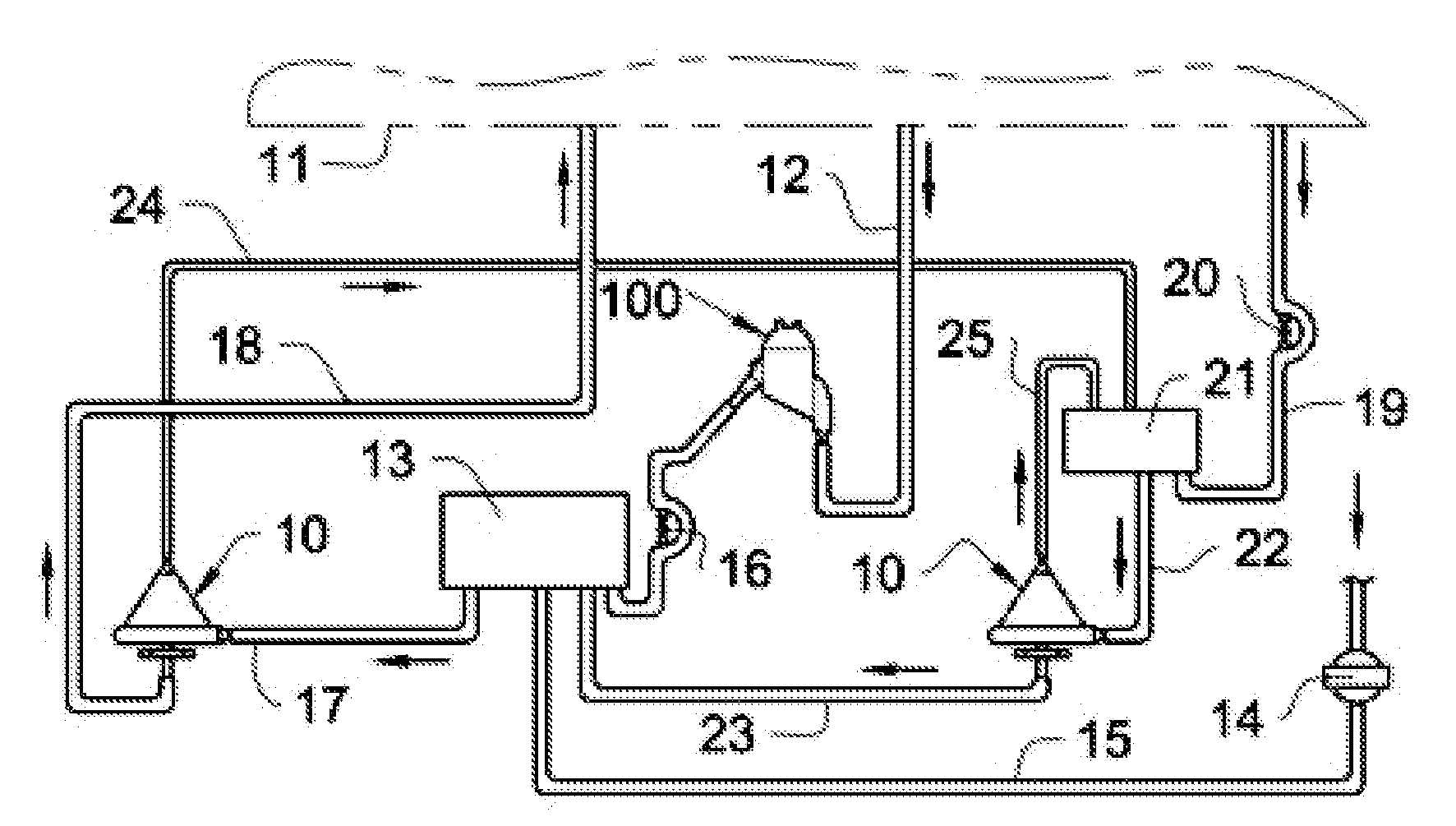
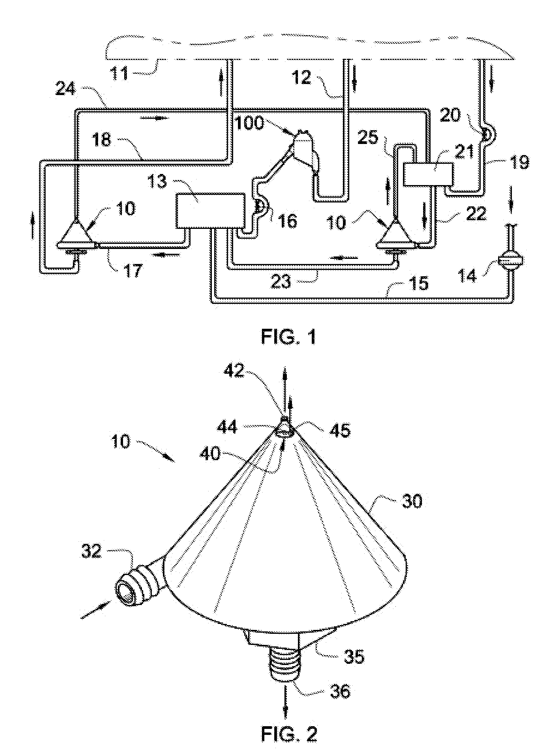
[0040]Referring now to the drawings and particularly to FIGS. 1-12, the preferred embodiments of the present invention are shown and generally designated by the reference numerals 10 and 100.

[0041]FIG. 1 illustrates the placement of the new and improved blood filter systems 10 and 100 in an extracorporeal circuit used during cardiopulmonary support procedures. One possible bypass circuit is described herewith, but other bypass circuits can also utilize the blood filter systems 10 and 100. In FIG. 1, a pump 16 draws blood from the patient 11 via tube 12 into blood filter system 100 where micro-bubbles, free gases and debris are removed before being pumped into an oxygenating device 13. The oxygenating device 13 removes carbon dioxide from the blood and introduces oxygen from an oxygen filter 14 and tube 15. Blood in oxygenating device 13 is then pumped into blood filter system 10 through tube 17 where micro-bubbles, free gasses and debris are further removed from the blood. Following...


PUM

PropertyMeasurementUnit
angleaaaaaaaaaa
anglesaaaaaaaaaa
anglesaaaaaaaaaa

Abstract

A blood filter system used for the sequential filtering of blood while actively removing air bubbles and debris comprising a filter housing with unique conical, or cylindrical shape, a flared inlet port, a unique up and down blood flow path, a multi-stage sequential filter assembly, an active air purge assembly and a unique downspout assembly with outlet port. The filter housing is adapted so that blood passes from the inlet port through the multi-stage sequential filter assembly to the outlet port following an up and down flow path, while its unique shape and angled filters effectively direct any air bubbles and debris up and out of the blood stream toward the active air purge assembly where they are removed.

Description

BACKGROUND OF THE INVENTION[0001]1. Field of the Invention[0002]The present invention relates to a blood filter system for use in connection with the filtration of blood in medical devices such as but not limited to extracorproreal circulation systems used during cardiopulmonary support Procedures. The blood filter system has particular utility in connection with the sequential filtering of blood while actively removing air bubbles and debris.[0003]2. Description of the Prior Art[0004]Blood filter systems for extracorporeal circulations are desirable for eliminating micro-bubble contamination and foreign particles from the patient's systemic circulation. It is critical that during any cardiopulmonary support procedures, there are no free gases, or air bubbles present in the blood returning to the patient. It is also critical that blood contacts the least amount of foreign surfaces and contains the least amount of dilution from the extracorporeal circulation system.[0005]The use of b...

Claims


Application Information

Patent Timeline
Patent Type & Authority Applications(United States)
IPC IPC(8): B01D37/00B01D19/00B01D35/00
CPCA61M1/3627B01D19/0042A61M1/3633
Inventor HERBST, DANIEL PATRICK
Owner HERBST DANIEL PATRICK
Why Eureka
Try Eureka