
Electrical rotating machine and electric vehicle

a technology of electric vehicles and rotating machines, applied in the direction of windings, dynamo-electric components, transportation and packaging, etc., can solve the problems of poor work efficiency, large variation in insulation properties, and paper insulation sheets may be conductive after burning to be carbonized, so as to improve fuel consumption and mileage

Inactive Publication Date: 2008-09-25
HITACHI LTD
View PDF3 Cites 38 Cited by
  • Summary
  • Abstract
  • Description
  • Claims
  • Application Information

AI Technical Summary

Benefits of technology

[0013]In the production of the electrical rotating machine of the present invention, at least a coil end portion of each partial coil is coated with an insulation layer before each partial coil is mounted in a slot, and the partial coils are connected to form a stator coil of an electrical rotating machine after mounted in the slots. In the production of the partial coil, an electric field lessening layer is formed on the coil conductor and an insulation layer is formed on the electric field lessening layer. Then, an electric field lessening layer is again formed on the insulation layer. An electric vehicle with improved fuel consumption and mileage can be realized by mounting the electrical rotating machine of the present invention therein.

Problems solved by technology

Hence, there is a problem that the sheet of insulation paper may be conductive after burned to be carbonized due to heat generated by the welding.
Further, the sheet of insulation paper has to be inserted manually, and hence there is another problem that work efficiency is poor and that variation in insulation property is large.
As a result, insulation failed units are produced.
Meanwhile, in the case of resin immersion or resin coating for insulation in the coil end portion, the coil end portion might not sufficiently be impregnated with resin because conductors at the coil end portion forming a complicated pattern are very close to each other.
In particular, there is a problem that the more compact the coil end becomes, the lower the probability on the coil end portion being fully impregnated with resin.
Hence, although having no problem at rated voltages of about several v to several tens of V, conventional low voltage electrical rotating machines using square shape wires are difficult to achieve higher rated voltages and higher output power to become on demand in the future.
Further, in recent years, as an electrical rotating; machine is often operated at various speeds making use of an inverter, surge voltages generated by the inverter cause unexpectedly high voltages to be applied between conductor turns inside and outside the slot.
These high voltages pose also a problem, which is difficult to overcome so far.

Method used


Image

  • Electrical rotating machine and electric vehicle
  • Electrical rotating machine and electric vehicle
  • Electrical rotating machine and electric vehicle

Examples


first embodiment

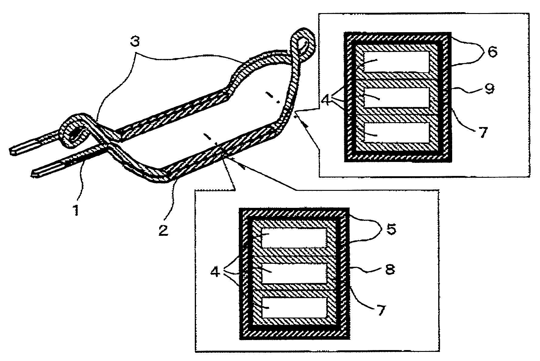
[0031]FIG. 1 shows a partial coil of an electrical rotating machine of the first embodiment. An electrical rotating machine coil 1 is made by covering with an electric field lessening layer 5 or 6 a coil conductor formed by winding a wire conductor 4 on itself a predetermined number of times, and then coating slot straight portions 2 of the coil conductor with an insulation layer 8 and coil end portions 3 of the coil conductor with an insulation layer 9, and finally coating them again with an electric field lessening layer 5 or 6.

[0032]An insulation film 7 over the wire conductor 4 can be such an enamel film as made of polyamide-imide, polyester imide, polyimide, polyester, and polyethylene naphthalate, or an enamel film containing inorganic fillers, or a impregnated glass fiber film with alkyd resin or the like. The electric field lessening layers 5 and 6 can be made of resin of epoxy, polyester, or acryl which contains such conductive or semiconductive fillers as made of carbon, i...

second embodiment

[0066]FIG. 5 shows a partial coil of an electrical rotating machine of the second embodiment. An electrical rotating machine coil 51 is made by coating a coil conductor formed by winding a wire conductor 4 on itself a predetermined number of times with an electric field lessening layer 55 or 56, and then coating slot straight portions 52 thereof with an insulation layer 58 and coil end portions 53 with an insulation layer 59. An insulation film 57 of the wire conductor 4 can be made of the same material as the insulation film 7 of the first embodiment.

[0067]Also in the second embodiment, because the insulation layers are formed before the partial coils are inserted unlike in a conventional low voltage electrical rotating machine using square shape wires, the burning of a sheet of insulation paper insulating the coil end portions or insulation failure due to failure in resin permeation does not occur. The second embodiment differs from the first embodiment in that no electric field l...

third embodiment

[0069]FIG. 6 shows a partial coil of an electrical rotating machine of the third embodiment. An electrical rotating machine coil 61 is made by winding a wire conductor 4 on itself a predetermined number of times to form a coil conductor and then coating slot straight portions 62 thereof with an insulation layer 68 and coil end portions 63 with an insulation layer 69. An insulation film 67 of the wire conductor 4 can be made of the same material as the insulation film 7 of the first embodiment.

[0070]Also in the third embodiment, because the insulation layers are formed before the partial coils are inserted unlike in a conventional low voltage electrical rotating machine using square shape wires, the burning of a sheet of insulation paper insulating the coil end portions or insulation failure due to failure in resin permeation does not occur. Embodiment 3 differs from the second embodiment in that no electric field lessening layer is formed on the wire conductor 4, and hence the share...


PUM


Abstract

An electrical rotating machine wherein the coil end portion and slot straight portion of a coil conductor are coated with insulation layers respectively. The insulation layers are different in thickness or insulation material, and an electric field lessening layer is coated on the coil conductor or the insulation layers.

Description

CLAIM OF PRIORITY[0001]The present application claims priority from Japanese application JP 2007-073852 filed on Mar. 22, 2007, the content of which is hereby incorporated by reference into this application.BACKGROUND OF THE INVENTION[0002]1. Field of the Invention[0003]The present invention relates to an electrical rotating machine.[0004]2. Description of the Related Art[0005]Demands for higher output power density in vehicles and general industrial electrical rotating machines have been increasing. In particular, for vehicles, the electrical rotating machine is not only a driving power but also itself a load, and hence higher output power density is required of the electrical rotating machine to improve fuel economy and mileage.[0006]There are two kinds of ways for achieving higher output power density in electrical rotating machines. One way is to make an electrical rotating machine smaller and to increase its output power. As to making the machine smaller, there is known a way w...

Claims


Application Information

Patent Timeline
IPC IPC(8): H02K3/40H02K3/32
CPCH02K3/345Y02T10/641H02K3/40H02K3/38Y02T10/64
Inventor OBATA, KOJI
Owner HITACHI LTD
Features
  • Generate Ideas
  • Intellectual Property
  • Life Sciences
  • Materials
  • Tech Scout
  • Unparalleled Data Quality
  • Higher Quality Content
  • 60% Fewer Hallucinations
Learn More