Symmetrical Multi-Path Method For Determining the Distance Between Two Transmitter-Receivers

a multi-path method and transmitter technology, applied in the direction of reradiation, using reradiation, measurement devices, etc., can solve the problems of special antennae, time expenditure, and inability to accurately measure distance, so as to reduce energy and channel bandwidth, avoid the effect of deterioration of accuracy

Active Publication Date: 2008-09-25
NANOTRON GES FUR MIKROTECHN
View PDF19 Cites 77 Cited by
  • Summary
  • Abstract
  • Description
  • Claims
  • Application Information

AI Technical Summary

Benefits of technology

[0018]A further object of the invention is to cite a method for determining distance which is distinguished within a transmission range in the order of magnitude of 10 km by increased accuracy of distance measurement compared with known methods and yet enables the use of clock generators with comparatively low frequencies in a range of approximately 100 MHz for measuring time in the subscribing transmitter-receivers.
[0019]A further object of the invention is to cite a method for determining distance which is distinguished within a transmission range in the order of magnitude of 10 km by increased accuracy of distance measuring compared to known methods and yet at the same time generates low energy consumption on the part of the participating transmitter-receivers.
[0020]A further object of the invention is to cite a method for determining distance which is distinguished within a transmission range in the order of magnitude of 10 km by increased accuracy of distance measurement compared with known methods and yet at the same time enables reasonably priced manufacture of the transmitter-receivers required for performing the method.

Problems solved by technology

Experience has shown that this method is too inaccurate and unreliable for measuring distance.
However, determining the distance of an object requires two cooperating devices at a known distance from one another.
Measuring the angle is relatively complicated (special antennae, time expenditure) and, because of interference, attenuation and reflections, inaccurate.
If there is no visual connection, measuring the angle is greatly restricted or no longer possible, depending on the medium used.
Experience has proved that this method is also too inaccurate and unreliable for measuring distance.
The transmission range of the systems is not very large, normal environmental influences such as daylight, sound sources or reflections interfere with them greatly and signal attenuations alone, e.g. due to thick smoke or haze, lead to the failure of these systems.
Owing to said disadvantages these methods are not suitable for precise and reliable measuring of distance.
Classical radar systems are considered disadvantageous as far as expenditure, immunity to interference and unambiguous identification of objects is concerned.
It is not possible to transmit all types of data with the classic radar systems.
Set up and operation of the infrastructure is very complicated and expensive.
Moreover, only determining their own position is possible, but not determining the position of remote objects.
In order to determine the distance from a remote object, an additional system is required to transmit messages, as this is not possible via the satellites.
The accuracy is additionally not estimated to be sufficiently precise, since the errors of two position determinations may accumulate in the distance calculation (1-3 m with differential GPS).
Furthermore, the equipment for determining position is distinguished by over-long measuring times of up to several minutes, making determining the distance of mobile objects too inaccurate or no longer possible.
Transmission of all types of data, as already mentioned, is not possible via the satellite-aided systems.
In addition, there is a dependency on the operator who may restrict the accuracy and reliability and charge fees for usage.
However, the attainable accuracy of determining position of at best 60 m is regarded as very disadvantageous.
Here too there is dependency on the operator, who nearly always charges fees for usage.
Very precise clock generators with an accuracy of more than ±1 ppm and therefore cost-intensive components are necessary to achieve high accuracy.
If reasonably priced clock generators (±50 ppm) were to be used, only inadequate accuracy (c.
However, the result of this is that fewer to no additional data at all can be transmitted and special message protocols have to be used.
Standardised message protocols cannot be used, which is a further considerable disadvantage of these methods in relation to recyclability or the capacity to extend standards.
Time counters faster in this way are regarded as very disadvantageous, though, as this is accompanied by an increase in energy consumption and costs of implementation.

Method used


Image

  • Symmetrical Multi-Path Method For Determining the Distance Between Two Transmitter-Receivers
  • Symmetrical Multi-Path Method For Determining the Distance Between Two Transmitter-Receivers
  • Symmetrical Multi-Path Method For Determining the Distance Between Two Transmitter-Receivers

Examples


case b

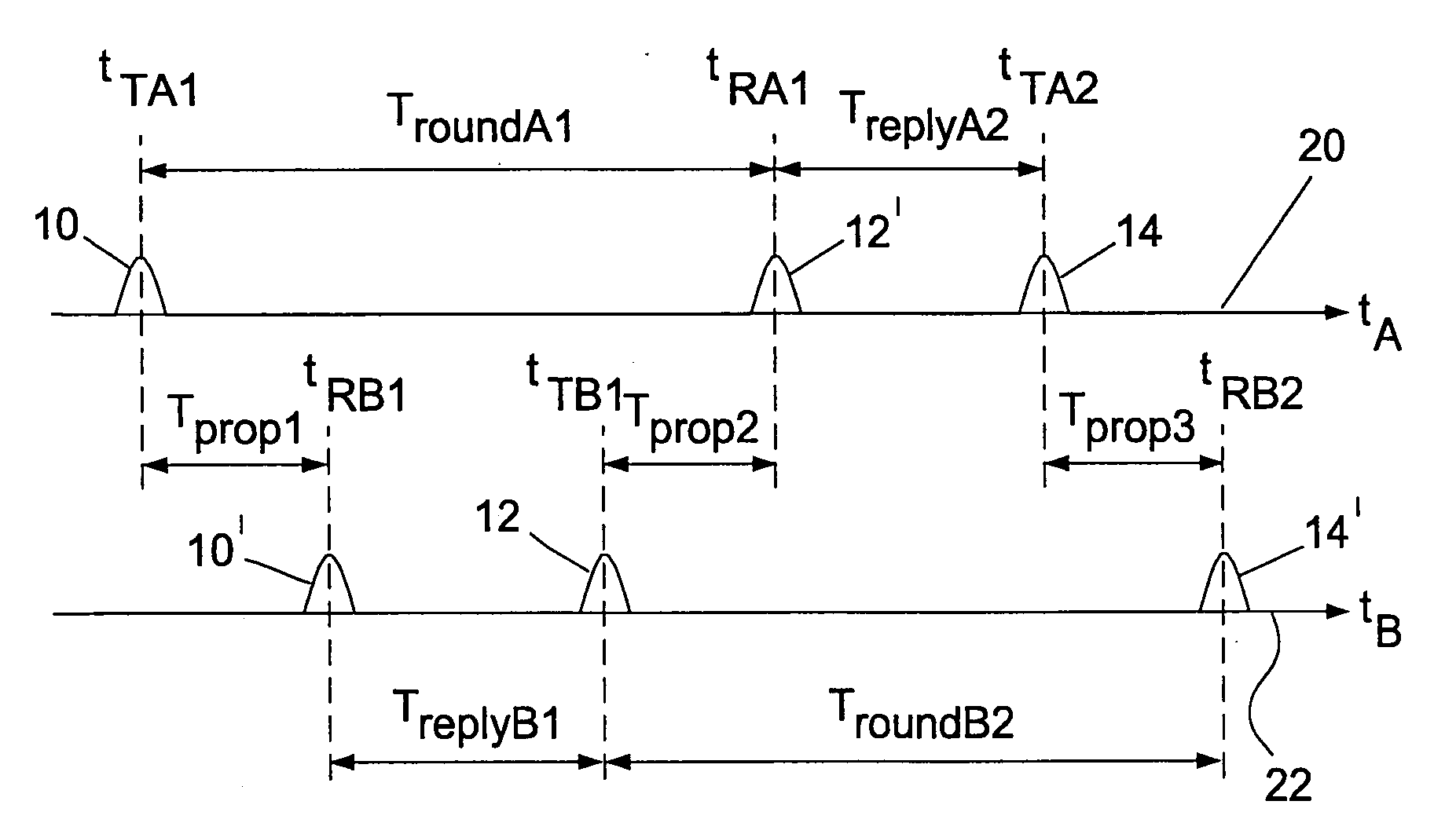
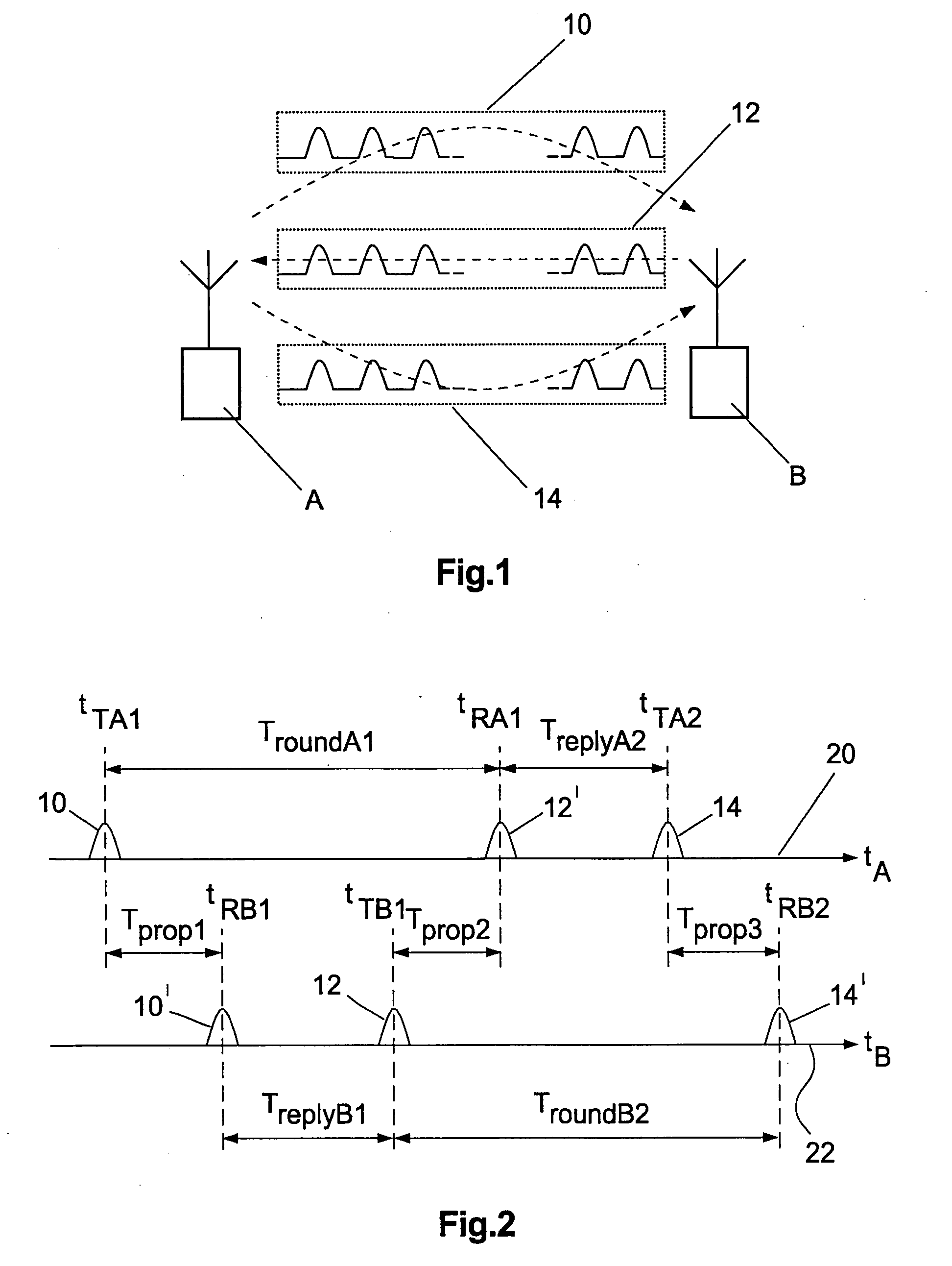
[0214]In case b) the relative error is substantially dependent on the ratio of the reply time difference (TreplyA−TreplyB) to the fourfold pulse transit time (see formula 14).

EtAB=TreplyA-TreplyB4Tprop(2EtA)Formula14

[0215]At this point a substantial advantage of the procedure according to the invention becomes evident: because of the adherence according to the invention to very small reply time differences, the precision of the distance measurement is improved. The precision of the distance measurement in the case of identical reply time intervals is not dependent on the absolute round and reply time intervals. An ideal case of identical time intervals is sufficiently enough approximated by adhering to a maximum difference between the reply time intervals of a maximum of 20 microseconds. Whereas the upper limit of 20 microseconds represents the currently preferred embodiment example, it should be pointed out that a distance measurement sufficiently accurate for many cases of applica...

first embodiment

[0350]In a first embodiment variant of a transmitter-receiver according to the invention illustrated in FIG. 14 several modules are combined in an integrated circuit device 100, also abbreviated to device, and implemented as an integrated circuit. An external CALC / APP module 102 is connected to the integrated device 100 via logical terminals Treply′, Tround′ and CTRL / DATA 104, 106 and 108. The logical terminals may be combined in a joint serial or parallel user interface.

[0351]An analogue transmitter 110 (TX) modulates the signal pulses to be transmitted to a carrier frequency and passes them amplified to an external antenna 112. An analogue receiver 114 performs amplification, demodulation and detection of radio pulses irradiated on to the antenna 112.

[0352]A baseband / MAC module 116 (MAC=medium access controller) performs coding of data frames to be transmitted and decoding of received data frames consisting of a sequence of radio signal pulses.

[0353]The baseband / MAC module 116 als...

second embodiment

[0362]In turn applications of wireless data transmission and distance measurement can additionally be integrated in the APP module 126. In the present second embodiment variant too the logical terminals d′124 and CTRL / DATA 108 can be combined in a joint serial or parallel user interface.

14.3 Integrated Distance Calculation and Application Module

[0363]FIG. 16 shows a further embodiment example of a transmitter-receiver which is distinguished by an integrated distance calculation and application module. The following illustration concentrates on differences in the transmitter-receiver of FIG. 16 compared with that of FIGS. 14 and 15. The same reference symbols are used for modules of equal functional value to the embodiment examples of FIGS. 14 and 15.

[0364]In the embodiment variant of FIG. 16 the CALC / APP module 102 (FIG. 14) is implemented in a device as an integrated circuit 130 in addition to the baseband / MAC module 120, the analogue transmitter 110 and the analogue receiver 114.

[...


PUM


Abstract

The invention relates to a symmetrical multi-path method for determining the spatial distance between two transmitter-receivers. Both transmitter-receivers set off at least one signal round in each case. A signal round comprises the steps:a) transmitting at least one request data frame of a first transmitter-receiver to a second transmitter-receiver at a request transmitting time (TTA1, TTB2),b) receiving the request data frame at the second transmitter-receiver at a request receiving time (TRB1, TRA2),c) transmitting a reply data frame from the second transmitter-receiver to the first transmitter-receiver at a reply transmitting time (TTB1, TTA2), which has a respective reply time interval (TreplyB1, TreplyA2) from the request receiving time (TRB1, TRA2) and detecting the reply time interval,d) receiving the reply data frame at the first transmitter-receiver setting off the signal round and detecting an allocated reply receiving time (TRA1, TRB2).The signal rounds are performed in such a way that the reply time intervals (TreplyA2, TreplyB1) are either identical or have a difference, in the case of performing more than one signal round set off by each transmitter-receiver an average difference, the amount of which is a maximum of 200 microseconds.

Description

TECHNOLOGICAL BACKGROUND OF THE INVENTION[0001]1. Domain of the Invention[0002]The invention relates to a method for determining the spatial distance of two transmitter-receivers communicating without wires from one another within a transmission range in the order of magnitude of 10 km. The invention further relates to a system of at least two transmitter-receivers communicating without wires, designed to determine the spatial distance of the transmitter-receivers from one another within a transmission range in the order of magnitude of 10 km. The invention finally relates to a transmitter-receiver for performing said method.[0003]2. Prior Art[0004]Three different media are employed to measure distances between mobile and stationary objects. These are: radio, infrared and ultrasound. The so-called pulse transit time method is mainly used for this. The transit time of transmitted pulses is determined by measuring the time of arrival (=TOA) and comparing it with the start time of the ...

Claims


Application Information

Patent Timeline
Patent Type & Authority Applications(United States)
IPC IPC(8): G01S13/76
CPCG01S7/28G01S13/765G01S13/76
Inventor MENZER, LARSIANELLI, ZBIGNIEWHACH, RAINER
Owner NANOTRON GES FUR MIKROTECHN
Why Eureka
Try Eureka