Eureka AIR delivers breakthrough ideas for toughest innovation challenges, trusted by R&D personnel around the world.

Equipment for pressurized adsorption and liquification of carbon dioxide from boiler flue gas for oil recovery by well injection

Inactive Publication Date: 2008-10-02
LIAOHE GASOLINEEUM EXPLORATION BUREAU
View PDF13 Cites 25 Cited by
  • Summary
  • Abstract
  • Description
  • Claims
  • Application Information

AI Technical Summary

Benefits of technology

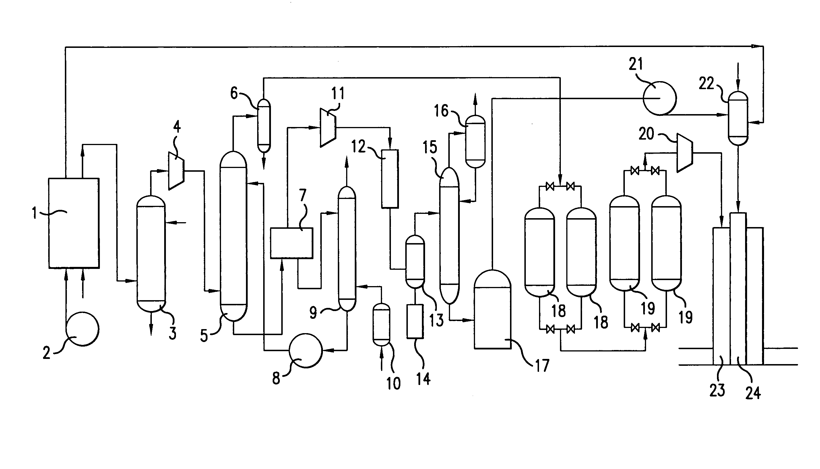
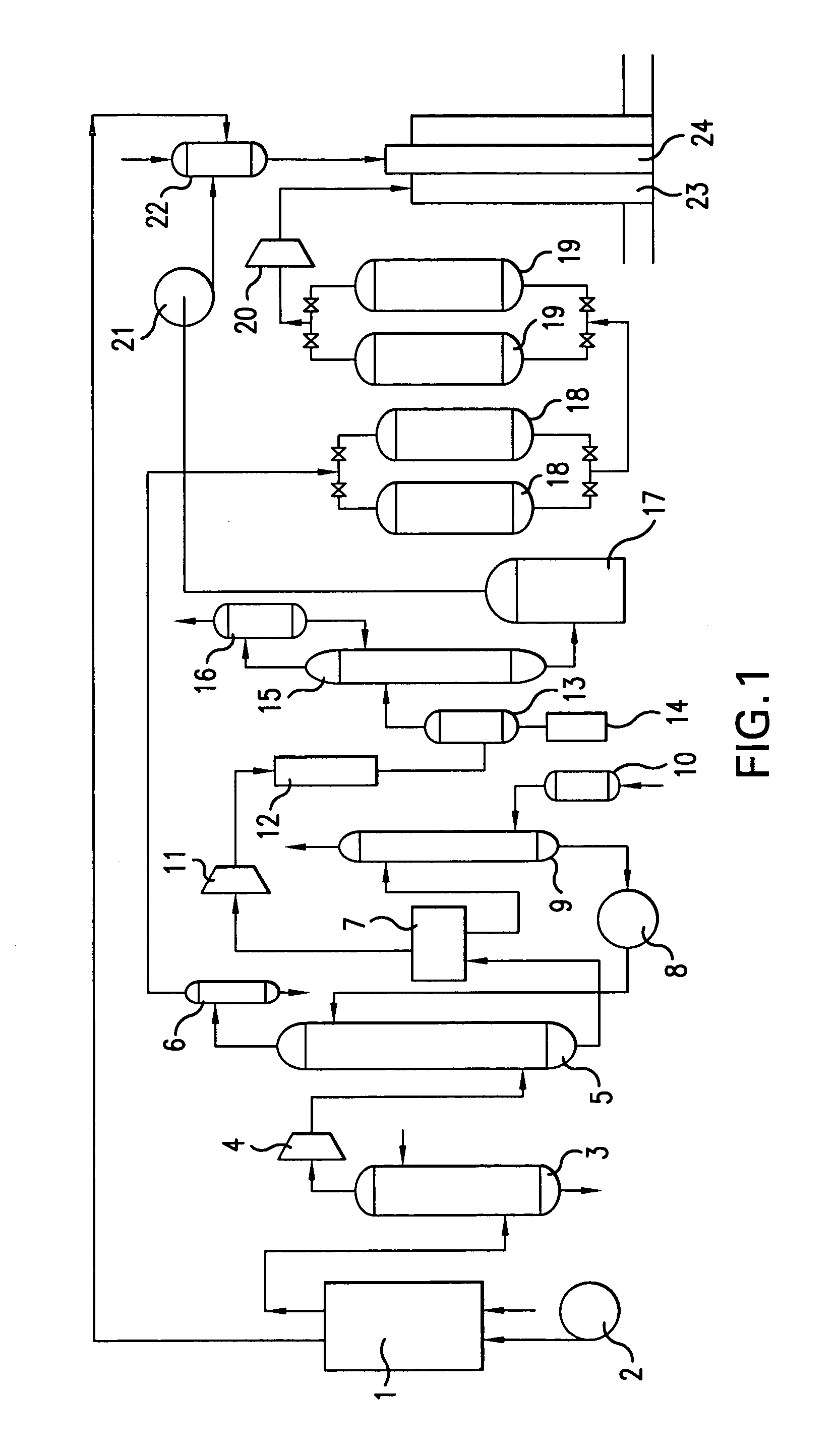
[0018]When the boiler is running, the produced steam may be directly injected into the thick crude oil well from the well head through steam transmission pipelines; the flue gas, after scrub, compression, adsorption and flash evaporation within the above process flow of the equipment, may produce a 98% (purity) concentration of carbon dioxide gas, which may be compressed, liquefied, rectified and stored, and then injected into the oil well after pressurized by pump. The end gas, after dried and absorbed, may produce a 96% (purity) concentration of nitrogen, which may be injected into the oil well after pressurized. The steam, carbon dioxide liquid and nitrogen obtained from the boiler step by step may be matched and injected into the well, thereby achieving the object of increasing the crude oil output.
[0019]With rational design and handsome practicability, the comprehensive mate equipment, when producing steam by the boiler, can obtain carbon dioxide liquid and nitrogen, thus realizing “single injection”, “double injection” or “triple injection” of steam, gaseous carbon dioxide and nitrogen and thereby gaining favorable results of crude oil output increase as well as environment protection.

Problems solved by technology

In addition, the exploitation of many oil fields has entered into the middle or later period: though a series of measures such as water or steam injection have been taken, the recovery efficiency of crude oil is still low, the exploitation cost is high, and a lot of original oil in-place is difficult to or even cannot be exploited economically.
Worse still, the recovery efficiency is even lower while the cost is even higher with regard to low permeable oil, thick crude oil as well as crude oil of condensate gas reservoirs.
However, the technology is, to a certain extent, restricted by economic factors for the rising price of gas hydrate (including natural gas), which, as a result, motivates the studies on the injection of other gases, especially carbon dioxide and nitrogen.
Unfortunately, for various reasons, in the prior art, oil recovery by CO2 or N2 is in the pre-feasibility study period as a single technology and mature technology or equipment has not been developed yet.

Method used


Image

  • Equipment for pressurized adsorption and liquification of carbon dioxide from boiler flue gas for oil recovery by well injection
  • Equipment for pressurized adsorption and liquification of carbon dioxide from boiler flue gas for oil recovery by well injection

Examples


Embodiment Construction

[0021]Given by the following implementary example, the invention is specified with reference to the appended FIGURE.

[0022]As is demonstrated by the FIGURE, the equipment provided by the invention for the pressurized adsorption and liquification of carbon dioxide from boiler flue gas for oil recovery by well injection comprises a boiler 1 for generating high pressure steam, a high pressure water pump 2, a tower scrubber 3, a compressor 4, an absorber 5, a separation tank 6, a flash pot 7, a solvent pump 8, a stripper 9, an air pump 10, a carbon dioxide compressor 11, a purifier 12, a liquefier 13, a congealer 14, a rectifying tower 15, a condenser 16, a storage tank 17, drying beds 18, a membrane module 19, a nitrogen pressurizer 20, a carbon dioxide pump 21 and a mixing tank 22.

[0023]The structure, assembly and installment of the equipment provided by the invention for the pressurized adsorption and liquification of carbon dioxide from boiler flue gas for oil recovery by well inject...


PUM

PropertyMeasurementUnit
Temperatureaaaaaaaaaa
Pressureaaaaaaaaaa

Abstract

An equipment for the pressurized adsorption and liquification of carbon dioxide from boiler flue gas for oil recovery by well injection comprising boiler for generating high pressure steam 1, high pressure water pump 2, tower scrubber 3, compressor 4, absorber 5, separation tank 6, flash pot 7, solvent pump 8, stripper 9, air pump 10, carbon dioxide compressor 11, purifier 12, liquefier 13, congealer 14, rectifying tower 15, condenser 16, storage tank 17, drying beds 18, membrane module 19, nitrogen pressurizer 20, carbon dioxide pump 21 and mixing tank 22. With rational design and handsome practicability, the comprehensive mate equipment, when producing steam by the boiler, can obtain carbon dioxide liquid and nitrogen, thus realizing “single injection”, “double injection” or “triple injection” of steam, gaseous carbon dioxide and nitrogen and thereby gaining favorable results of crude oil output increase as well as environment protection.

Description

FIELD OF THE INVENTION[0001]This invention relates to an equipment for oil well exploitation, especially one for the reclaim of boiler flue gas and mated for thick crude oil (or called “dense” crude oil) recovery by steam injection.BACKGROUND OF THE INVENTION[0002]In oil fields, the reservoir bed belonging to the continental facies bears considerable heterogeneity during the process of sedimentation. Part of the crude oil containing water has fast rising velocity for its high viscosity. In addition, the exploitation of many oil fields has entered into the middle or later period: though a series of measures such as water or steam injection have been taken, the recovery efficiency of crude oil is still low, the exploitation cost is high, and a lot of original oil in-place is difficult to or even cannot be exploited economically. Worse still, the recovery efficiency is even lower while the cost is even higher with regard to low permeable oil, thick crude oil as well as crude oil of con...

Claims


Application Information

Patent Timeline
IPC IPC(8): B01D51/10
CPCB01D53/62B01D53/73B01D53/75B01D53/77B01D2253/10B01D2257/302B01D2257/504B01D2257/80E21B43/164F23J2900/15061Y02C10/04Y02P90/70Y02C20/40
Inventor ZHANG, FENGSHANGAO, YUANWEN
Owner LIAOHE GASOLINEEUM EXPLORATION BUREAU
Why Eureka
Eureka Blog
Learn More