Method for manufacturing porous silicon carbide sintered body
a technology of porous silicon carbide and sintered body, which is applied in the field of manufacturing a porous silicon carbide sintered body, can solve the problems of not being able to obtain the strength necessary to maintain a structured body with thin walls, raising serious problems for construction machines, and affecting the environment and the human body
- Summary
- Abstract
- Description
- Claims
- Application Information
AI Technical Summary
Problems solved by technology
Method used
Image

Examples
first embodiment
[0045]In the order of manufacturing processes, the following description will discuss a first embodiment, one embodiment of the present invention.
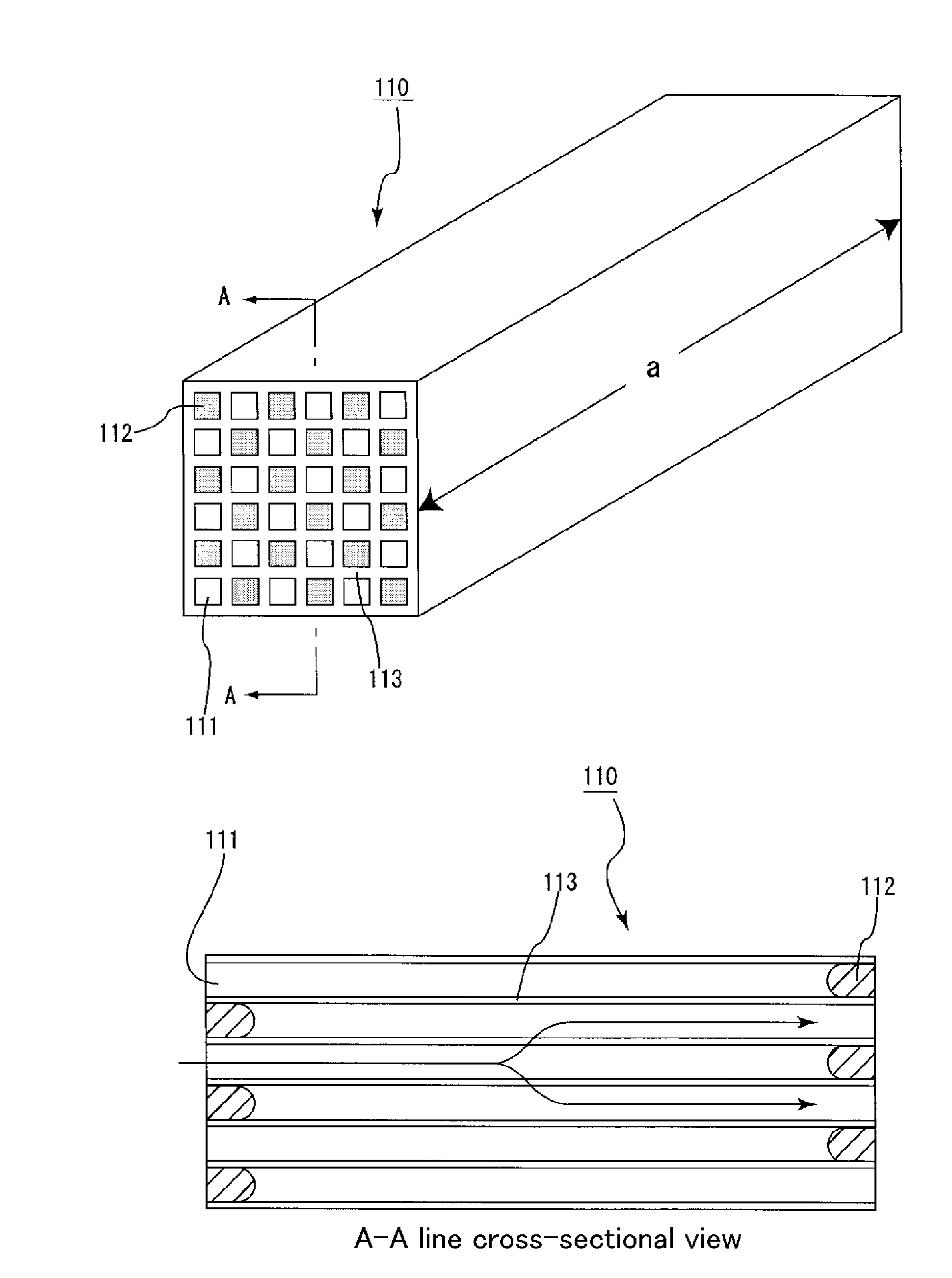
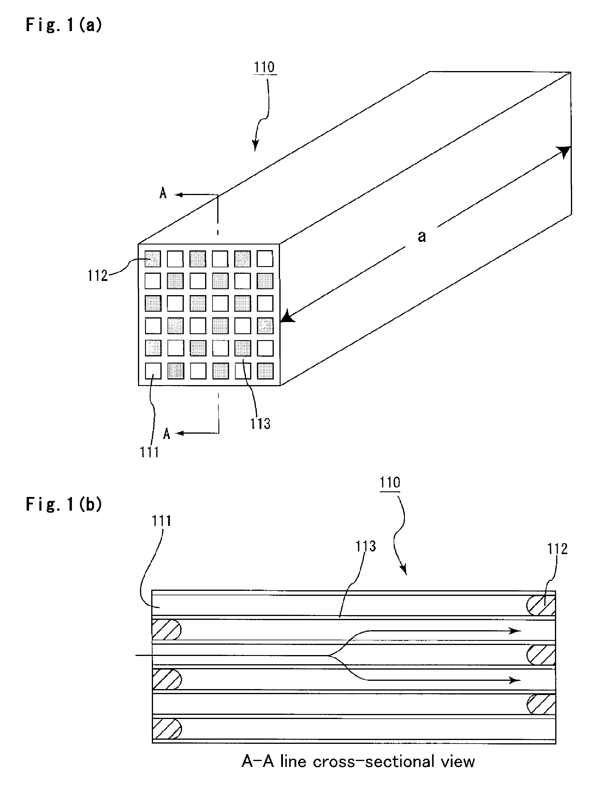
[0046]In the first embodiment, a porous silicon carbide sintered body shown in FIGS. 1(a) and 1(b) is manufactured. FIG. 1(a) is a perspective view that schematically shows one example of a porous silicon carbide sintered body to be manufactured by a manufacturing method according to the embodiment of the present invention, and FIG. 1(b) is an A-A line cross-sectional view of FIG. 1(a).
[0047]As shown in FIG. 1(a), a porous silicon carbide sintered body 110 has a structure in which a large number of cells 111 are disposed in parallel with one another in a longitudinal direction (the direction shown by an arrow a in FIG. 1(a)), and a cell wall 113 that separates the cells 111 is allowed to function as a filter.
[0048]That is, as shown in FIG. 1(b), each of the cells 111, formed in the porous silicon carbide sintered body 110, is sealed with a...
example 1
[0077]An amount of 70 kg of α-type silicon carbide powder having an average particle diameter of 20 μm, 29 kg of α-type silicon carbide powder having an average particle diameter of 0.5 μm, 20 kg of an organic binder (methylcellulose) and 1 kg of silicon powder having an average particle diameter of 3 μm (made by Kanto Metal Corporation) were mixed by using a wet mixing machine so that mixed powder was prepared.
[0078]Next, separately, 12 kg of a lubricant (UNILUB, made by NOF Corporation), 5 kg of a plasticizer (glycerin) and 65 kg of water were mixed to prepare a liquid mixture, and this liquid mixture and the mixed powder were mixed by using a wet mixing machine so that a raw material composition was prepared.
[0079]In this raw material composition, the content of silicon powder to the total amount of silicon carbide powder and silicon powder was 1% by weight.
[0080]Next, the raw material composition was charged into an extrusion molding machine equipped with a die used for extrusio...
second embodiment
[0096]In this embodiment, the firing treatment was carried out by setting the firing temperature in the Fifth Process of the first embodiment in a range of 2200 to 2300° C.
[0097]In the case of the firing temperature of less than 2200° C., the sintering of silicon carbide powder tends not to proceed; in contrast, in the case of the firing temperature of more than 2300° C., the sintering process of silicon carbide powder tends to proceed excessively. Moreover, since the power consumption increases, this state is disadvantageous from the economic viewpoint. However, the firing temperature is 2200 to 2300° C., it is possible to manufacture a porous silicon carbide sintered body having a desired pore diameter with reduced fluctuations.
[0098]Here, also in the present embodiment, the same effects as those of (1) to (6) of the first embodiment can be obtained.
[0099]The following description will discuss Examples that more specifically disclose the second embodiment of the present invention....
PUM
| Property | Measurement | Unit |
|---|---|---|
| temperature | aaaaa | aaaaa |
| particle diameter | aaaaa | aaaaa |
| particle diameter | aaaaa | aaaaa |
Abstract
Description
Claims
Application Information
 - R&D
- Intellectual Property
- Life Sciences
- Materials
- Tech Scout
- Unparalleled Data Quality
- Higher Quality Content
- 60% Fewer Hallucinations
Browse by: Latest US Patents, China's latest patents, Technical Efficacy Thesaurus, Application Domain, Technology Topic, Popular Technical Reports.
© 2025 PatSnap. All rights reserved.Legal|Privacy policy|Modern Slavery Act Transparency Statement|Sitemap|About US| Contact US: help@patsnap.com