

Induction of differential stress resistance and uses thereof
- Summary
- Abstract
- Description
- Claims
- Application Information
AI Technical Summary
Benefits of technology
Problems solved by technology
Method used
Image

Examples
example 1
A Starvation Response-Based Differential Stress resistance method to enhance cancer Treatment
Material and Methods
Cell Lines
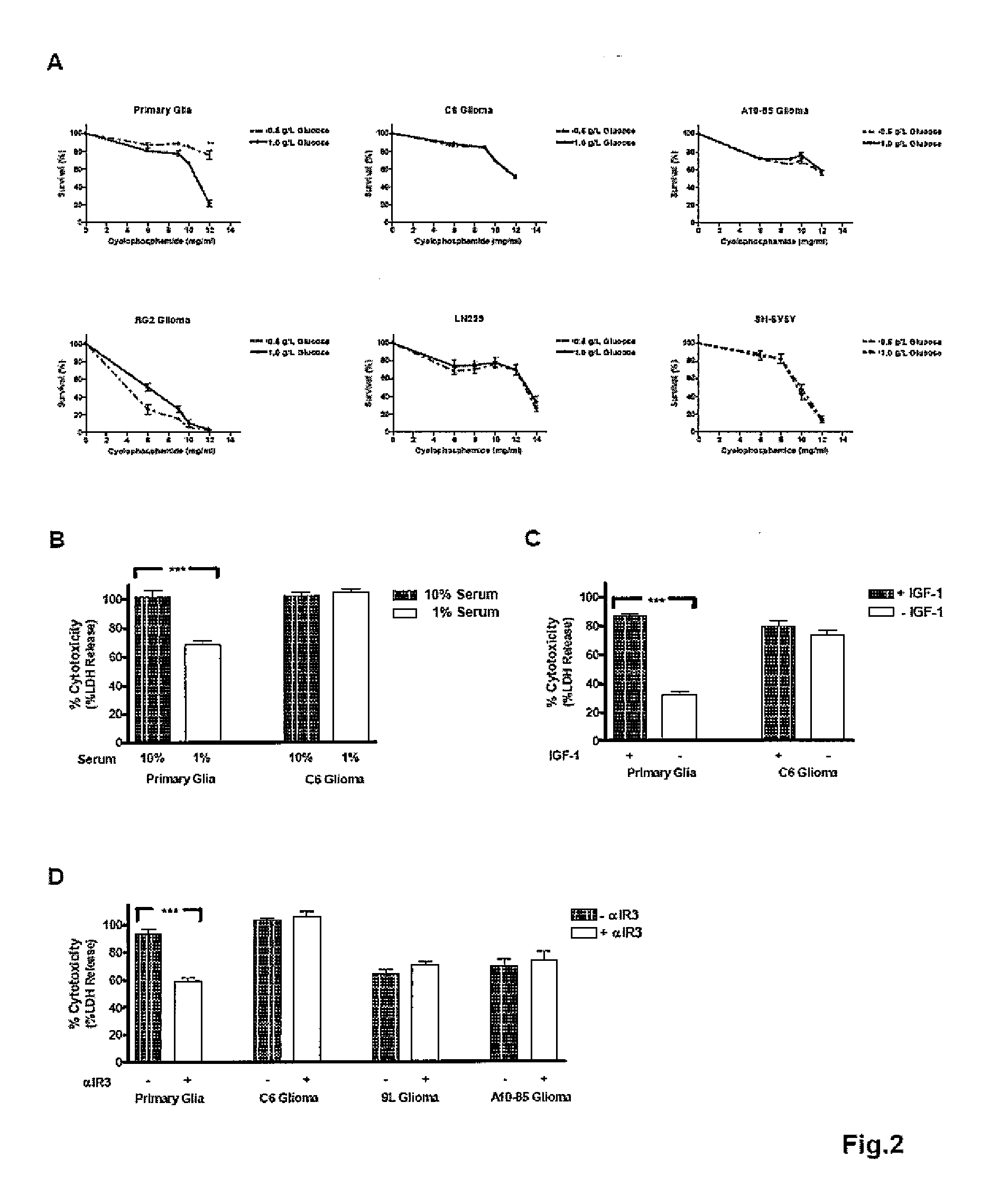
[0059]Primary mixed glial cells were obtained from the cerebral cortex of 1 to 3 day old Sprague Dawley rat pups (Charles River) as described before. Cells cultured for 10-14 days in DMEM / F12 medium with 10% fetal bovine serum (FBS) were used in assays. C6, A10-85, 9L and RG2 rat glioma cell lines and LN229 human glioma cell line and SH-SY5Y human neuroblastoma cell line were maintained in DMEM / F12 medium with 10% FBS at 37° C. under 5% CO2.
STS Treatments
[0060]Cells were seeded into 96-well microtiter plates at 20,000-30,000 cells / well and incubated for 2 days. Cells were washed with phosphate buffered saline (PBS) prior to treatments as indicated in the text. All treatments were performed at 37° C. under 5% CO2.
[0061]Glucose restriction was done by incubating cells in glucose free DMEM (Invitrogen) supplemented with either low glucose (0.5 gL) or normal glucose...
example ii
Starvation and IGF-I Reduction Protect Normal But not Cancer Cells Against High Dose Chemotherapy
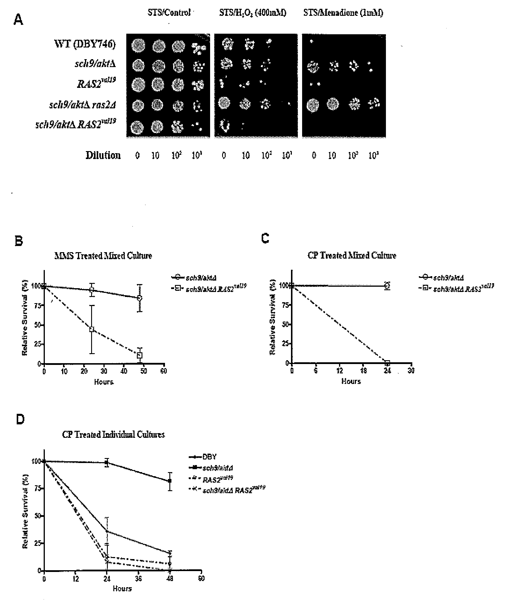
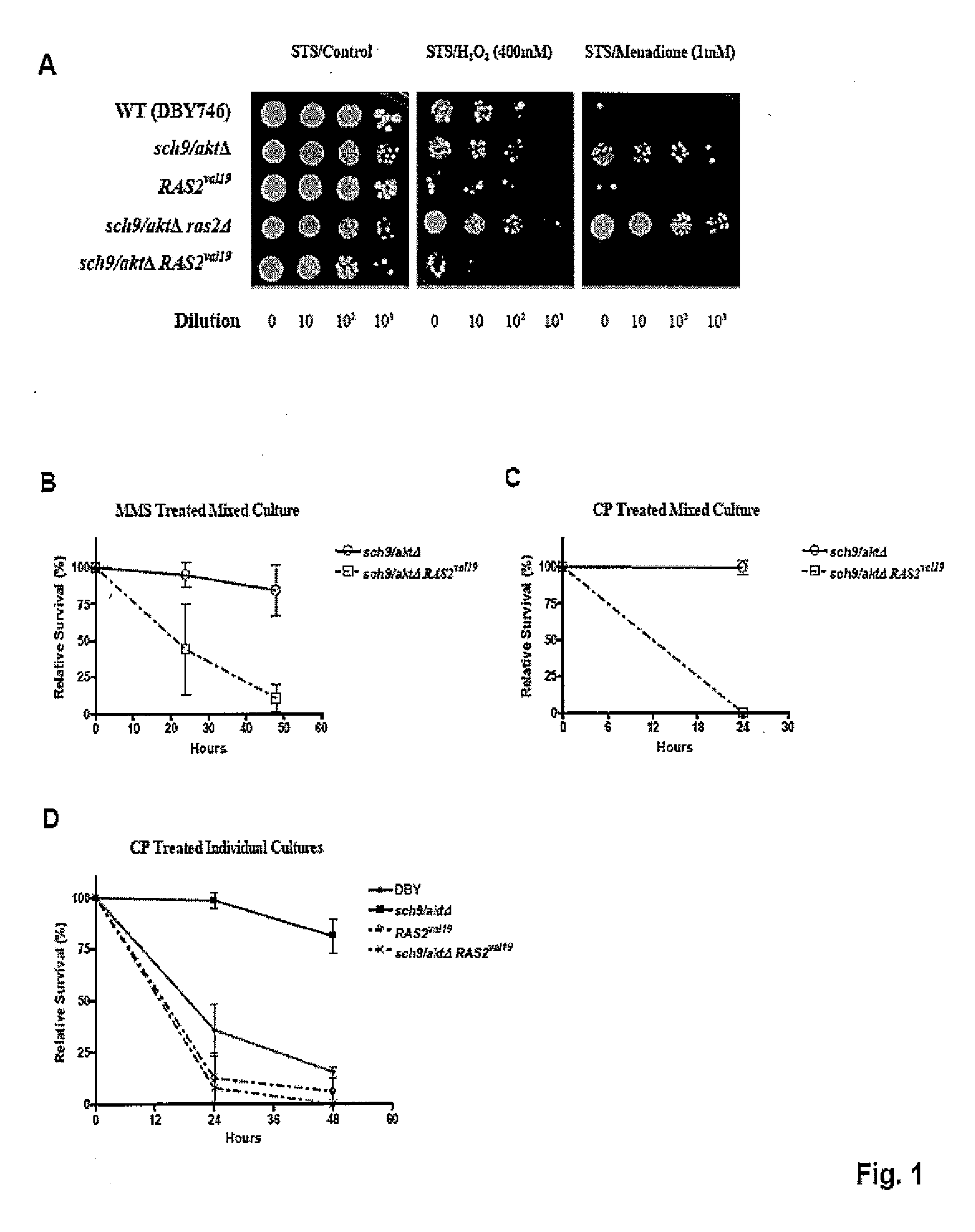
[0128]The inventor's studies in S. cerevisiae and those of others in worms, flies, and mice have uncovered a strong association between life span extension and resistance to multiple stresses. This resistance is observed in long-lived yeast cells lacking the orthologs of the human Ras (RAS2) and Akt (SCH9 / AKT) proto-oncogenes and in long-lived worms and mice with reduced activity of homologs of the IGF-I receptor (IGFIR), which functions upstream of Ras and Akt in mammalian cells, and is also implicated in many human cancers. This resistance is also observed in model systems in which the calorie intake is reduced by at least 30%.
[0129]To test whether constitutively active oncogenes or oncogene homologs can prevent the switch to a protective maintenance mode in response to starvation, it was first determined whether acute starvation would be as effective in increasing stress resistance as...
example iii
Materials and Methods
[0186]Yeast strains and Growth Conditions. All the experiments were performed using yeast of DBY746 background. Knockout strains were prepared with standard PCR-mediated gene disruption protocol. Strains used in this study:
StrainGenotypeDBY746MATa, leu2-3, 112, his3Δ1, trp1-289, ura3-52,GAL+sch9 / aktΔDBY746 sch9::URA3ras2ΔDBY746 ras2::LEU2tor1ΔDBY746 tor1::HIS3RAS2val19DBY746 RAS2val19 (CEN, URA3)*tor1ΔRAS2val19DBY746 ras2::LEU2 RAS2val19 (CEN, URA3)*sch9 / aktΔRAS2val19DBY746 sch9::URA3 RAS2val19 (CEN, URA3)*SCH9 / AKTDBY746 SCH9 (CEN, URA3)**pRS416-RAS2val19 was constructed by inserting 1.9 kb ClaI-HindIII fragment from pMF100 into pRS416.
[0187]Yeast cells were grown in minimal medium (SC) containing 2% glucose and supplemented with amino acids as described previously. For short term starvation (STS) treatment, day 1 cultures (24 hours after initial OD=0.1 inoculation) were washed 3 times with sterile distilled water, resuspended in water, and incubated at 30° C. w...
PUM
| Property | Measurement | Unit |
|---|---|---|
| Fraction | aaaaa | aaaaa |
| Fraction | aaaaa | aaaaa |
| Fraction | aaaaa | aaaaa |
Abstract
Description
Claims
Application Information