
Renewable energy system for hydrogen production and carbon dioxide capture

a technology of carbon dioxide capture and hydrogen production, applied in the direction of energy input, waste based fuel, electrochemical generators, etc., can solve the problems of generating several tons of carbon dioxide pollution per ton of manufactured base, abundant chlorine, toxic, etc., and achieve the effect of eliminating atmospheric carbon and no carbon dioxid

Inactive Publication Date: 2008-10-09
SULFURCYCLE INTPROP HLDG CO LLC
View PDF53 Cites 136 Cited by
  • Summary
  • Abstract
  • Description
  • Claims
  • Application Information

AI Technical Summary

Benefits of technology

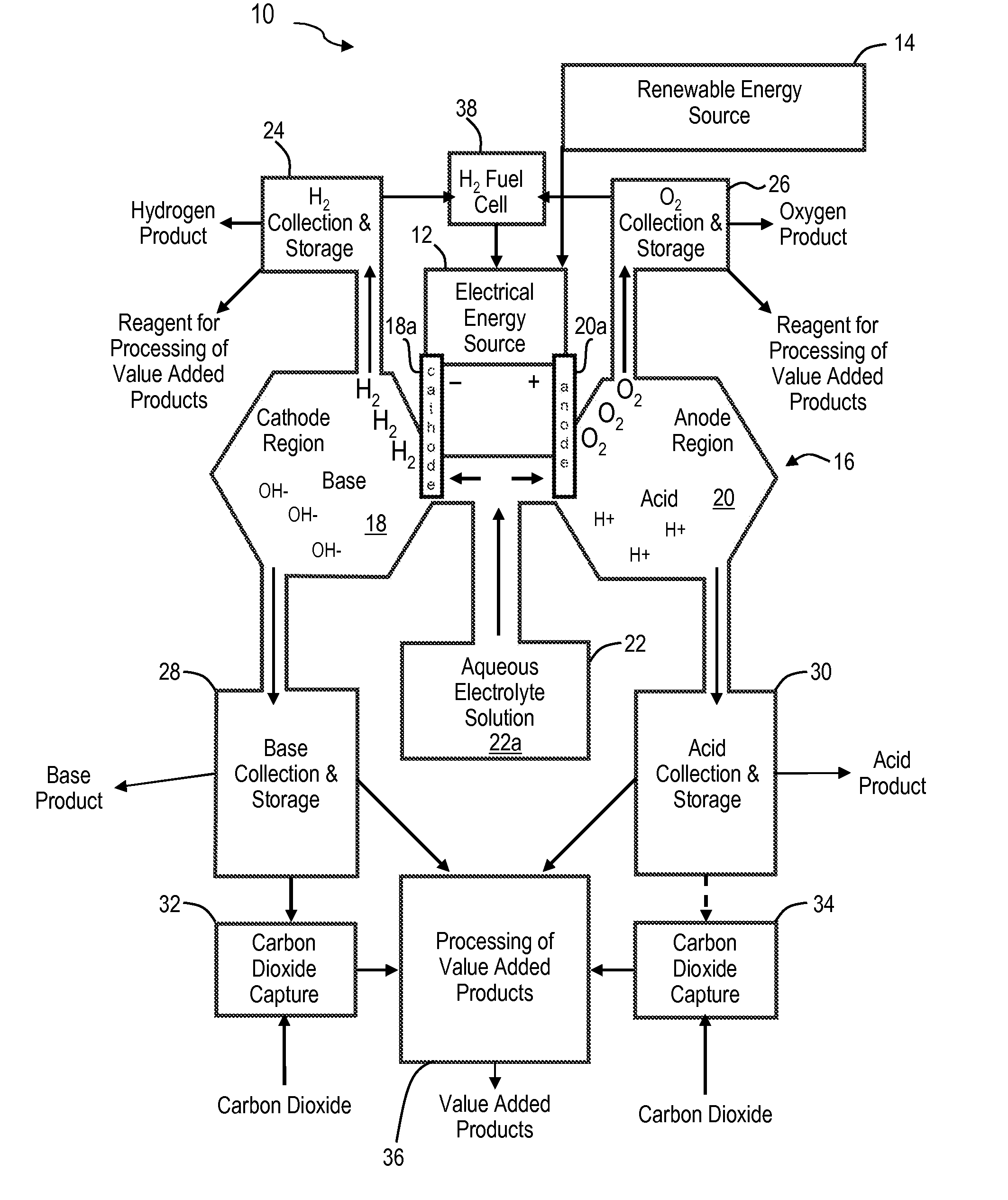
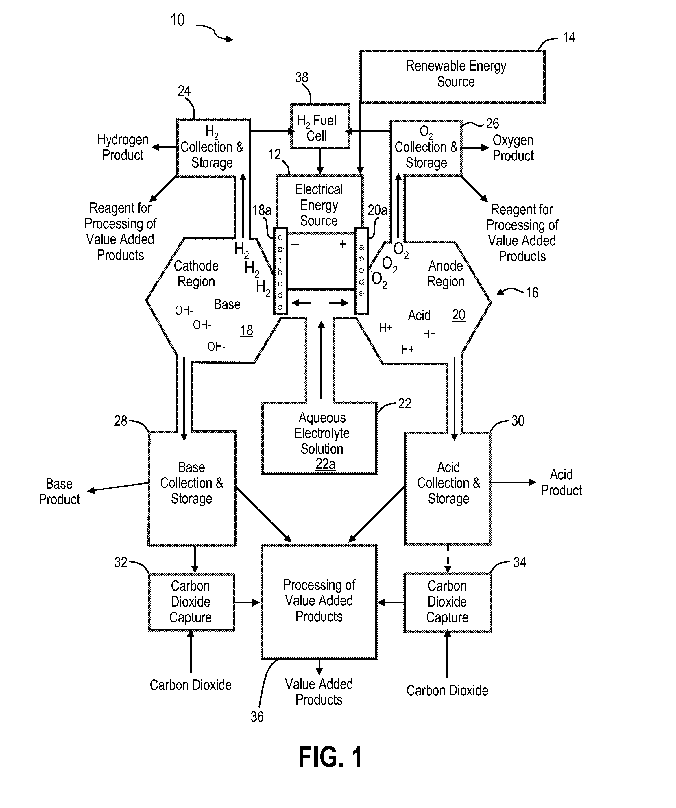
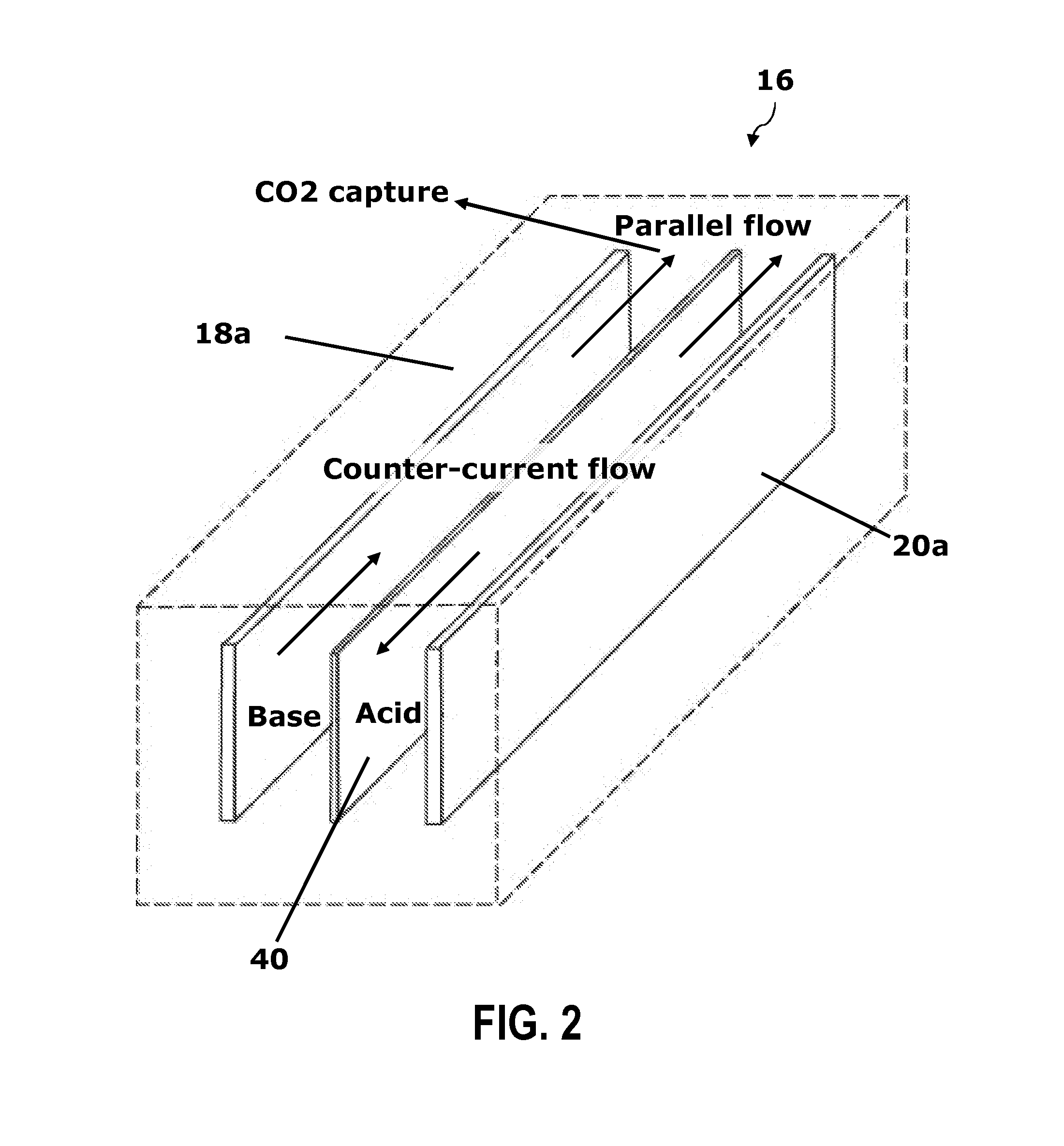
"The present invention is an integrated system for producing hydrogen and removing carbon dioxide using an energy source and a water source with ionic electrolytes. The system produces no carbon dioxide and uses a renewable energy source. The system also includes a water electrolysis process that produces hydrogen gas, oxygen gas, a base, and an acid, which are sequestered. The carbon dioxide in the atmosphere is converted to a value-added product using the base. The system captures more carbon dioxide than it produces and produces less than about 100 mg of chlorine per liter of electrolyte. The invention provides a solution for reducing carbon dioxide emissions and producing value-added products."

Problems solved by technology

While effective, the chloralkali method generates abundant chlorine, a toxic by-product, and generates several tons of carbon dioxide pollution per ton of manufactured base when powered with electricity generated from fossil fuels.

Method used


Image

  • Renewable energy system for hydrogen production and carbon dioxide capture
  • Renewable energy system for hydrogen production and carbon dioxide capture
  • Renewable energy system for hydrogen production and carbon dioxide capture

Examples


example 1

[0044]A water electrolysis cell, shown in FIG. 6, was constructed to demonstrate the feasibility of generating concentrated acid and base for carbon dioxide trapping. It consisted of a vertical central electrolyte feed tube about 2.5 centimeters (cm) in diameter, connected near its base to upward slanting anode and cathode tubes attached opposite one another. Wire, screen or flat, linear electrodes consisting of nickel, stainless steel or platinum were placed in the anode and cathode tubes near their points of attachment to the central tube. A concentrated, chloride-free electrolyte solution of aqueous sodium sulfate was introduced to the system via the central feed tube, creating an electrically conductive cell in which water was oxidized at the anode and reduced at the cathode. A small 15-watt solar panel was used to provide renewable electricity to the system.

[0045]When a DC current from the solar panel was applied to the system, hydrogen and hydroxide base were produced rapidly ...

example 2

[0048]A second example used a 1-inch diameter glass tube sealed at the bottom with a porous glass frit. The frit allowed fluid and ion exchange between the inside and outside of the glass tube, creating an inner anode or cathode cell. Flat nickel or platinum electrodes were placed on opposite sides of the glass frit and attached to a 15 W DC photovoltaic panel or DC power supply. This system created a water electrolysis device that produced concentrated base inside the tube and concentrated acid outside the tube.

[0049]Depending on mode of operation, a pH differential of over 11 was quickly generated in this system; an acid-base concentration gradient of over 20 billion fold. The electrolyte inside the tube reached a pH of about 13, while across the frit, less than ¼ inch away, the electrolyte pH reached about 1.6. Vigorous production of hydrogen and oxygen were also observed.

example 3

[0050]A third example included a two-chamber flow-through system constructed from machined plastic. A peristaltic pump was used to circulate electrolyte solution into the anode and cathode chambers, which were physically separated by a semi-permeable membrane or filter. Variable width plastic spacers were used to vary the gaps between the electrodes and the membrane. A nickel-copper alloy was initially used as electrode material. Hydrogen and oxygen were collected at valves at the top of the device, and acid and base were continually circulated past the electrodes until sufficient concentrations were reached. A variable output DC power source was used to generate voltages sufficient to electrolyze water.

[0051]pH differentials of over about 10 units were quickly achieved and maintained in this system. The nickel-copper electrodes proved susceptible to corrosion at certain voltages. Corrosion-resistant nickel, platinum, alloy or stainless steel electrodes would be more suitable for us...


PUM

PropertyMeasurementUnit
voltageaaaaaaaaaa
voltageaaaaaaaaaa
DC voltagesaaaaaaaaaa

Abstract

The present invention is an integrated system for the production of hydrogen and the removal of carbon dioxide from the air or gas streams. The integrated system includes an energy source for generating electrical energy and a water source coupled to the energy source. The water source includes ionic electrolytes. The energy source supplies energy to the water source to electrolyze water to produce hydrogen gas, oxygen gas, acid and base. The carbon dioxide reacts with the base. In some embodiments, the energy source is a renewable energy source. The integrated system produces substantially no carbon dioxide and when combined with a renewable energy source, produces clean hydrogen fuel and reduces atmospheric carbon dioxide, resulting in carbon dioxide negative energy and manufacturing strategies.

Description

[0001]This application claims the benefit under 35 U.S.C. 119(e) of U.S. Provisional Patent Application No. 60 / 921,598, filed on Apr. 3, 2007, entitled A NOVEL ELECTROCHEMICAL METHOD FOR REMOVING CARBON DIOXIDE FROM GAS STREAMS AND SIMULTANEOUSLY GENERATING HYDROGEN GAS, which is herein incorporated by reference in its entirety.CROSS-REFERENCE TO RELATED APPLICATIONS[0002]This application is related to co-owned and co-pending application entitled ELECTROCHEMICAL APPARATUS TO GENERATE HYDROGEN AND SEQUESTER CARBON DIOXIDE, filed on the same day and assigned Ser. No. ______ and to co-owned and co-pending application entitled ELECTROCHEMICAL METHODS TO GENERATE HYDROGEN AND SEQUESTER CARBON DIOXIDE, filed on the same day and assigned Ser. No. ______, both of which are herein incorporated by reference in their entirety.FIELD OF THE INVENTION[0003]The present invention relates to the fields of renewable hydrogen production and carbon dioxide capture and sequestration. More specifically, ...

Claims


Application Information

Patent Timeline
Patent Type & Authority Applications(United States)
IPC IPC(8): C25B1/00
CPCC25B1/04H01M8/0656H01M16/003Y02E60/368C25B15/08Y02E70/10Y02E50/346C25B15/02Y02E60/50Y02E50/30Y02P20/133Y02E60/36
Inventor LITTLE, C. DEANEHEFFERNAN, TIMOTHY C.KOSMOSKI, JOSEPH V.LITTLE, C. GORDON
Owner SULFURCYCLE INTPROP HLDG CO LLC
Learn More