Conical-shaped impact mill

a cone-shaped, impact mill technology, applied in the direction of grain treatment, manufacturing tools, applications, etc., can solve the problems of rapid temperature rise of particles, inability to control the extent of comminution, and ineffective jet mills, etc., to achieve the effect of reducing belt slippage and excessive nois

Active Publication Date: 2008-10-09
LEHIGH TECH INC
View PDF6 Cites 17 Cited by
  • Summary
  • Abstract
  • Description
  • Claims
  • Application Information

AI Technical Summary

Benefits of technology

[0025]In accordance with a further embodiment of the present invention an impact mill is provided with a base portion upon which is disposed a rotor rotably mounted in a bearing assembly. The conical shaped rotor has an upwardly aligned conical surface portion coaxial with the rotational axis. A plurality of impact knives are mounted on the conical surface. The impact mill is provided with an outer mill casing which supports a conical grinding track assembly which surrounds the rotor. The mill casing has a downwardly aligned cylindrical collar which may be axially adjusted to set a grinding gap between the rotor and the grinding track assembly. To mitigate belt slippage and excessive noise when operating at high speeds, the rotor shaft of the impact mill is provided with a sprocketed drive sheave wherein the rotor is rotated by a synchronous sprocketed belt, in communication with a power source, accommodated on the sprocketed drive sheave.

Problems solved by technology

Jet mills, although effective, cannot control the extent of comminution.
This oftentimes results in the production of an excess percentage of undersized particles.
In view of the fact that the cryogenic temperatures attained by the frozen particles are much lower than the ambient surrounding temperature of the mill, this temperature gradient results in a rapid temperature rise of the particles.
During that period the temperature of the particles is increased, reducing comminution effectiveness.
Another problem associated with comminution mills in general and conical mills of the type described above in particular is the inability to alter the physical configuration of the impact mill to adjust for specific particle size requirements of the various materials.
This is usually difficult or impractical given the physical limits of the impact mill design.
An associated problem, related to alteration of rotor configuration in order to effect changes in desired product particle size, is ease of replacement of worn or damaged portions of the impact mill.
As in the case of replacement of parts of any mechanical device, problems are magnified in proportion to the size and complexity of the part being replaced.
Yet another problem associated with impact mills resides in power transmission to effectuate rotation of the rotor.
Present designs employ multiple belt or gear power transmission means which are oftentimes accompanied by unacceptable noise levels.
A corollary of this problem is that if power transmission speeds are reduced to abate excessive noise, rotor speed is reduced so that comminution results are unacceptable.

Method used


Image

  • Conical-shaped impact mill
  • Conical-shaped impact mill
  • Conical-shaped impact mill

Examples


Embodiment Construction

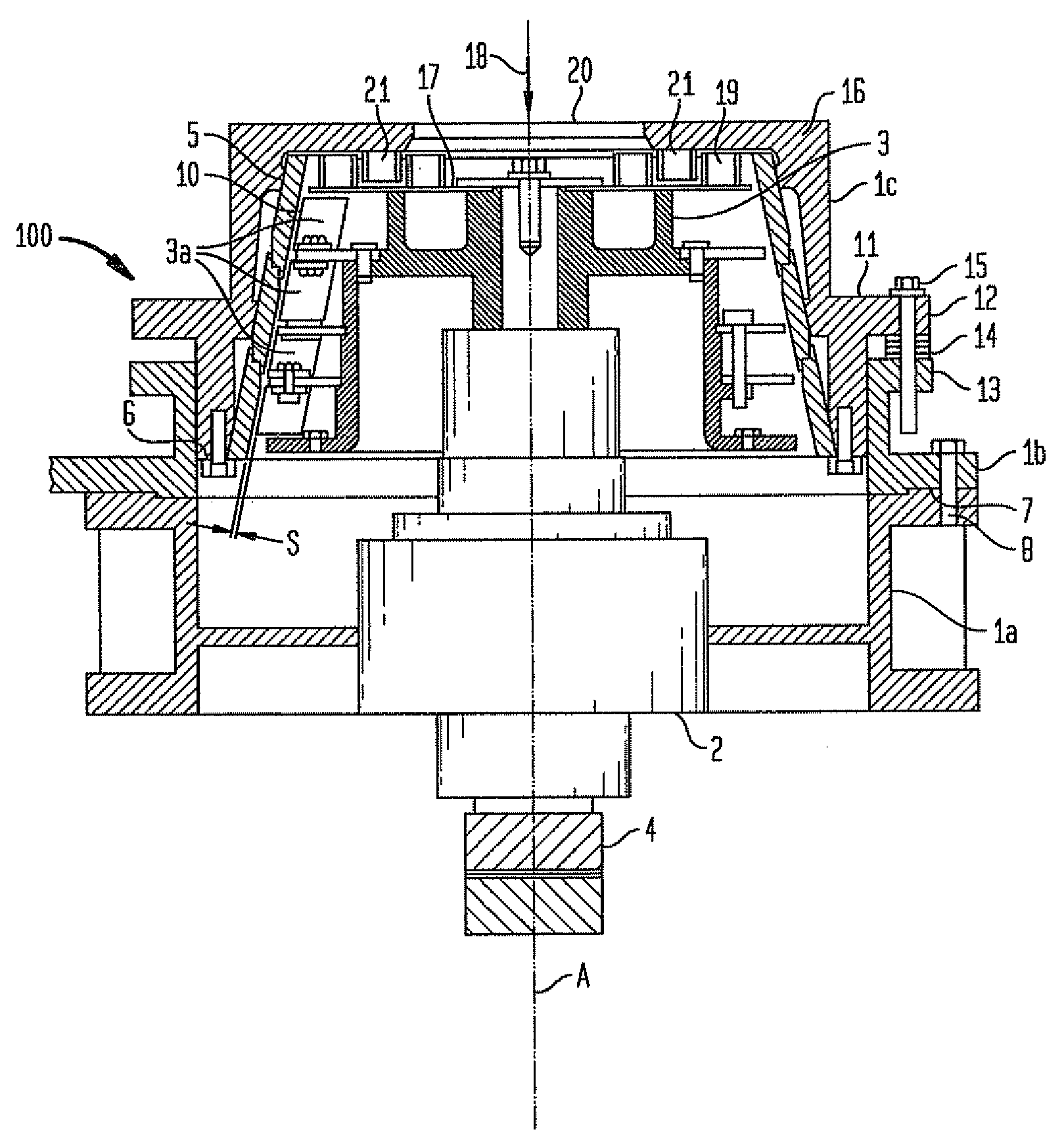
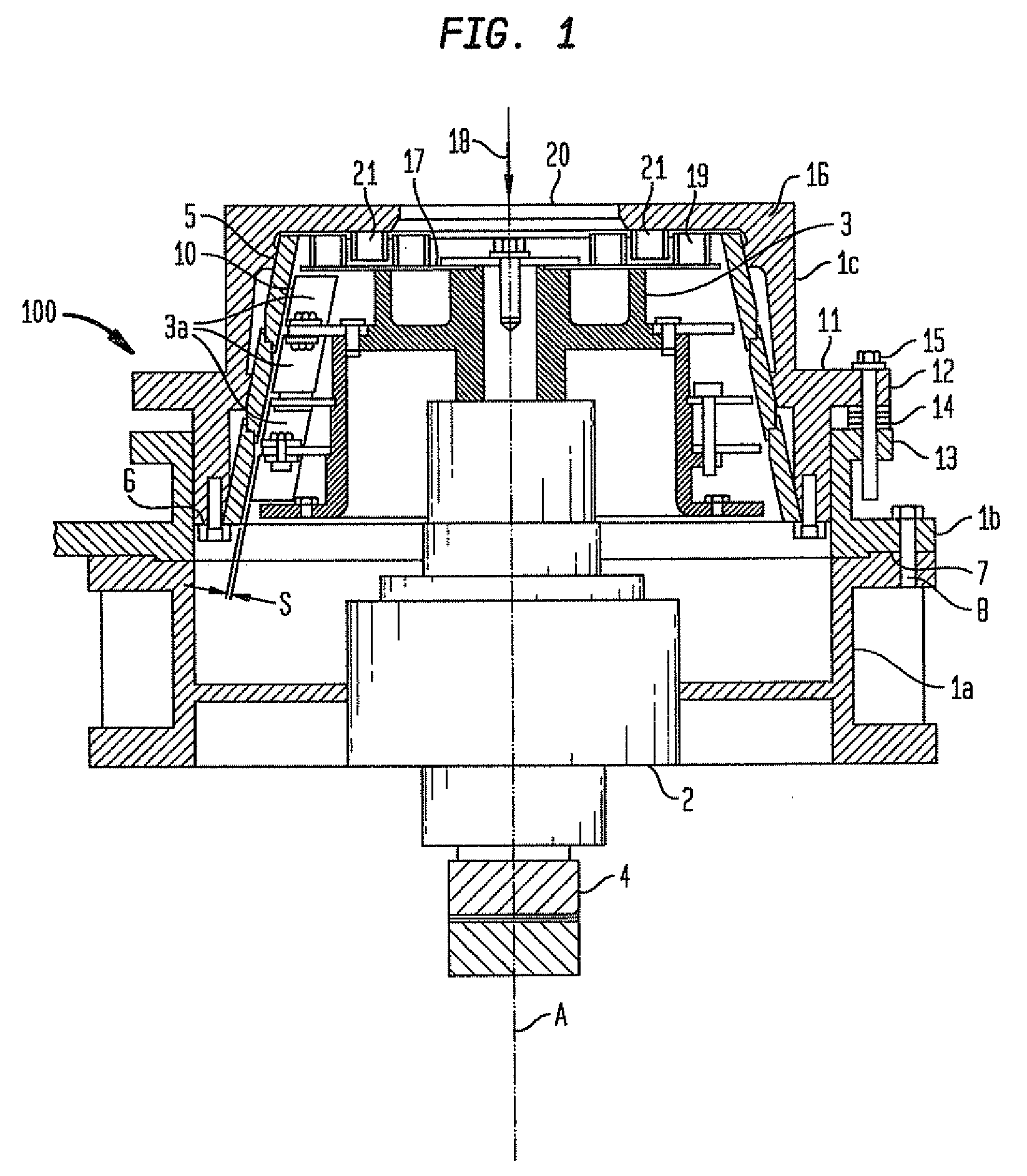
[0036]An impact mill 100 includes three housing sections: a lower base portion section 1a, a center housing section 1b and a top housing section 1c. The lower base portion section 1a carries a bearing housing 2 in which a rotor 3 is rotatably mounted. The center housing section 1b is concentrically nested 7 in the lower housing section 1a and provides concentric vertical alignment for the upper housing section 1c. A plurality of bolts 8 is provided for the detachable connection of the two housing sections. The top housing section 1c provides a concentric tapered nest for a conical grinding track assembly 5. The conical grinding track assembly 5 is securely connected to the top housing section 1c at its lower end 6. The rotor 3 is driven by a motor 34 by means of a belt 32 and a sheave 4 provided at the lower end of the rotor shaft.

[0037]The top section 1c includes the conical grinding track assembly 5. The grinding track assembly 5 has the shape of a truncated cone. Grinding track a...


PUM


Abstract

An impact mill including a base portion on which is disposed a rotor rotatably mounted in a bearing housing, the rotor having an upwardly aligned cylindrical surface portion coaxial with the rotational axis. The impact mill is provided with a mill casing within which is located a conical track assembly which surrounds the rotor to form a conical grinding path. The mill casing is provided with a downwardly aligned cylindrical collar which may be axially adjusted to set a grinding gap between the rotor and the mill casing. The rotor is provided with a plurality of impact knives complementary with a plurality of impact knives disposed on the inside top surface of the mill casing. In addition, the impact mill can be formed of separated conical sections. Finally, power is transmitted to the rotor of the impact mill by a synchronous sprocketed belt, accommodated by a sprocketed drive sheave, wherein the belt is in communication with a power source.

Description

BACKGROUND OF THE INVENTION[0001]1. Field of Invention[0002]The present invention is directed to a device for comminution of solids. More particularly, the present invention relates to a conically-shaped impact mill.[0003]2. Description of the Prior Art[0004]Devices for providing comminution of particulate solids are well known in the art. Amongst the many different milling devices known in the art grinding mills, ball mills, rod mills, impact mills and jet mills are most often employed. Of these, only jet mills do not rely on the interaction between the particulate solid and another surface to effectuate particle disintegration.[0005]Jet mills effectuate comminution by utilization of a working fluid which is accelerated to high speed using fluid pressure and accelerated venturi nozzles. The particles collide with a target, such as a deflecting surface, or with other moving particles in the chamber, resulting in size reduction. Operating speeds of jet milled particles are generally ...

Claims


Application Information

Patent Timeline
Patent Type & Authority Applications(United States)
IPC IPC(8): B02C13/00
CPCB02C13/14B02C13/18B02C13/282B02C2013/28681B02C13/2804
Inventor WAZNYS, PETER J.FISCHER, JOSEFCIALONE, ANTHONY M.
Owner LEHIGH TECH INC
Why Eureka
Try Eureka